Accua
A micro-ecosystem that gives you food
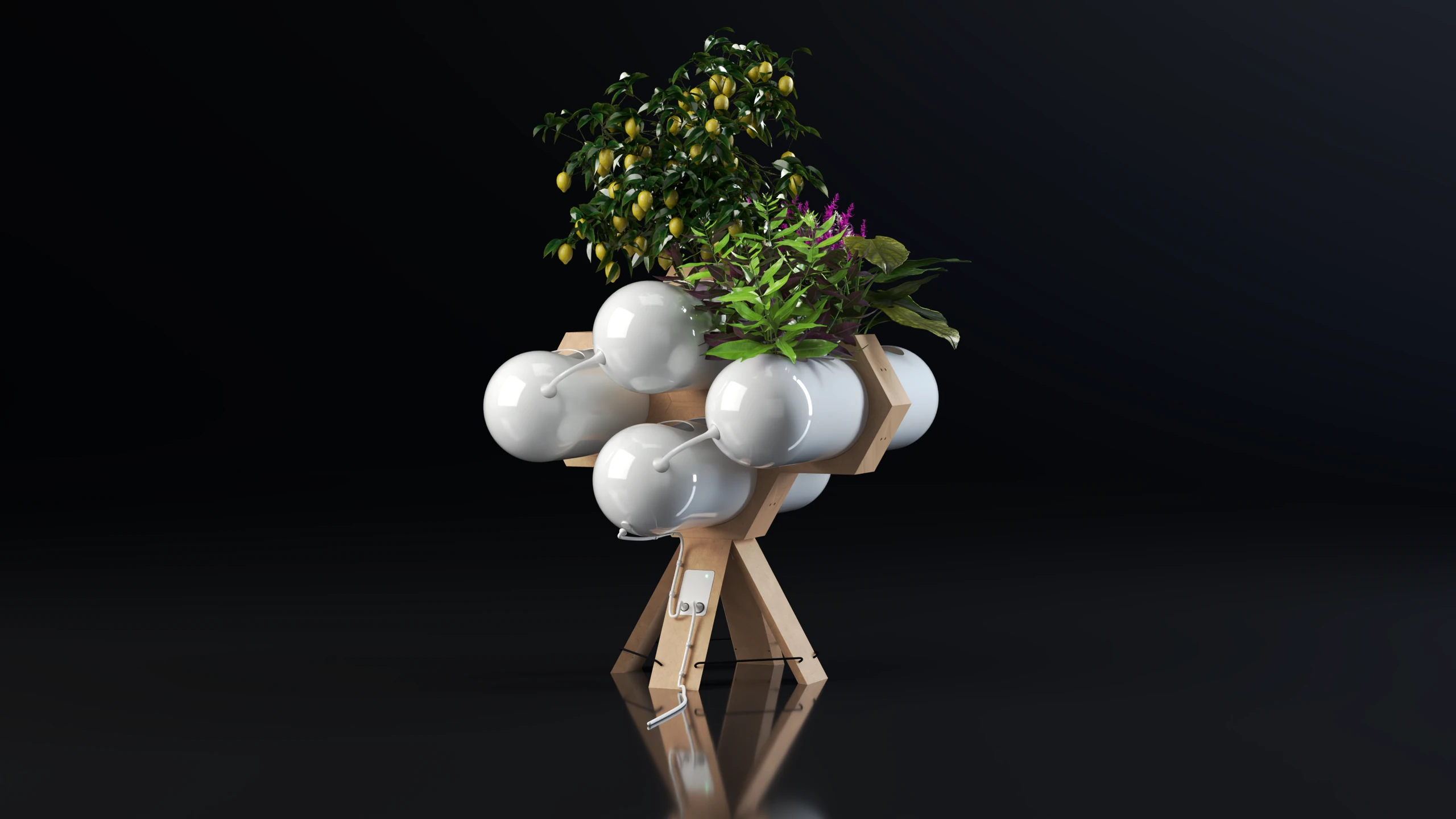
A closed-loop aquaponics system, ACCUA concentrates a complete food supply with very little energy use.
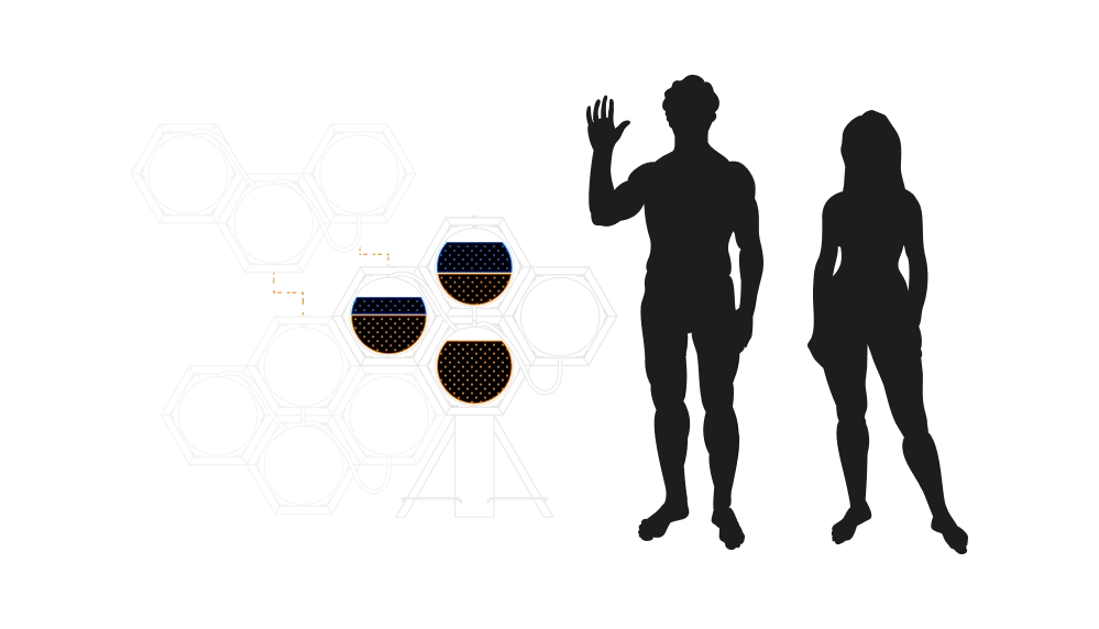
The closed water system needs only enough maintenance to replace the water lost to evaporation.
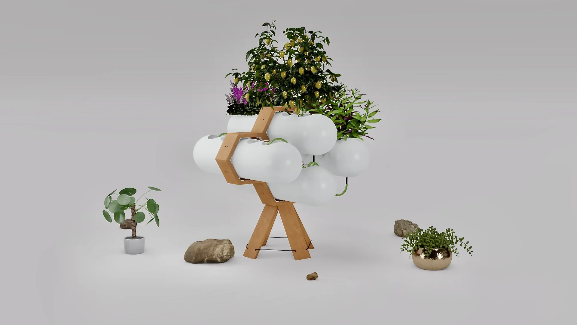
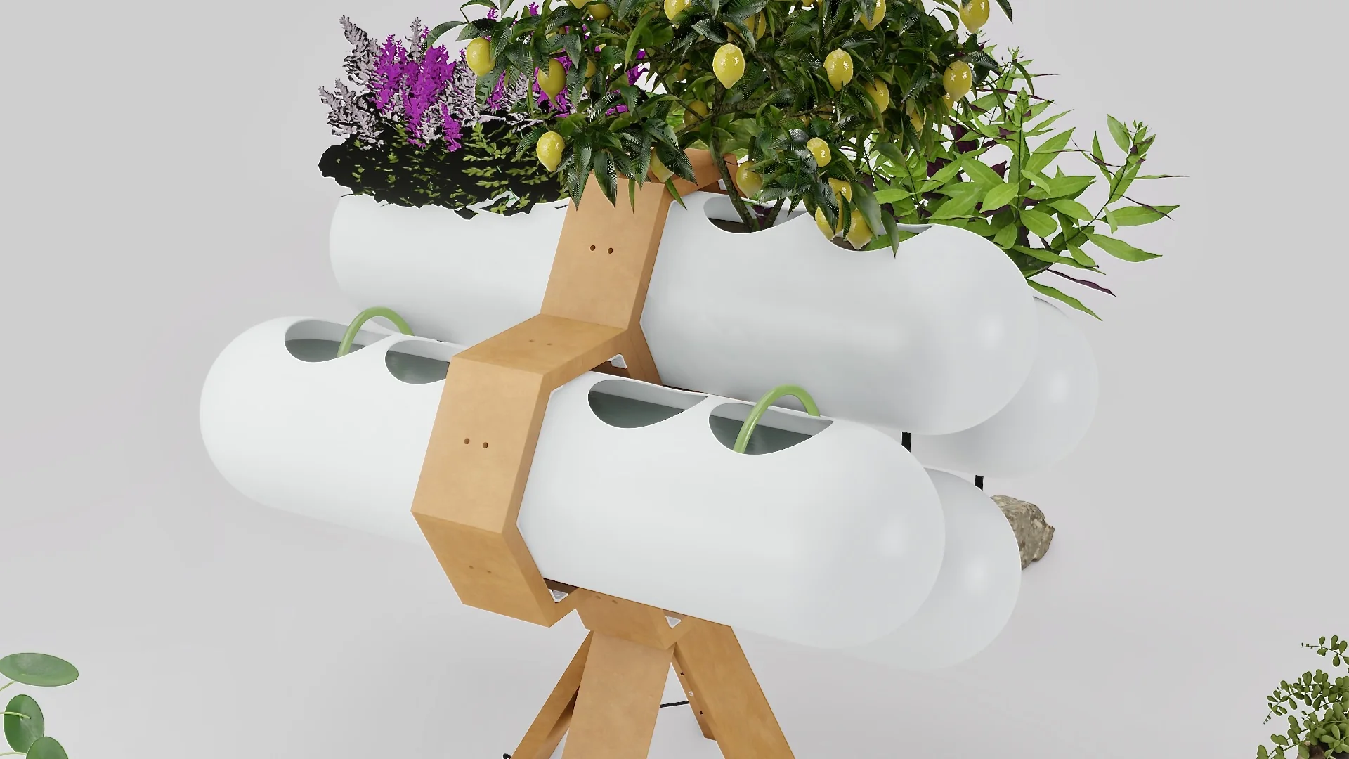
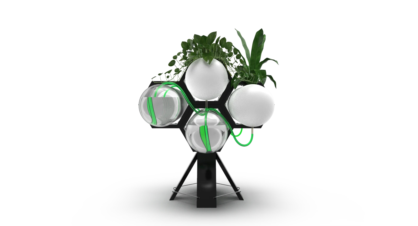
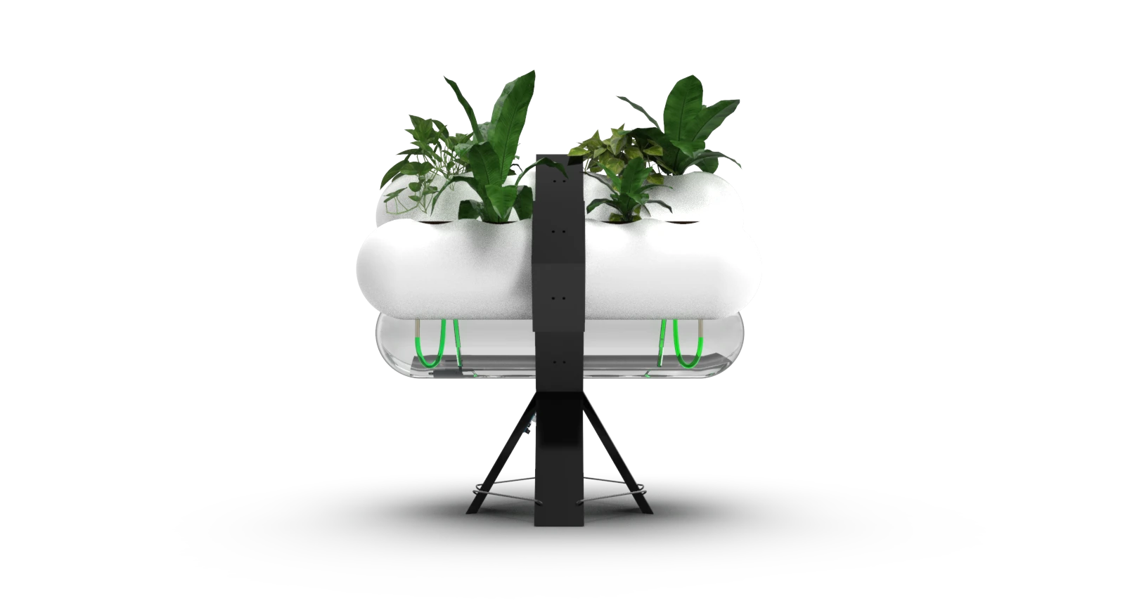
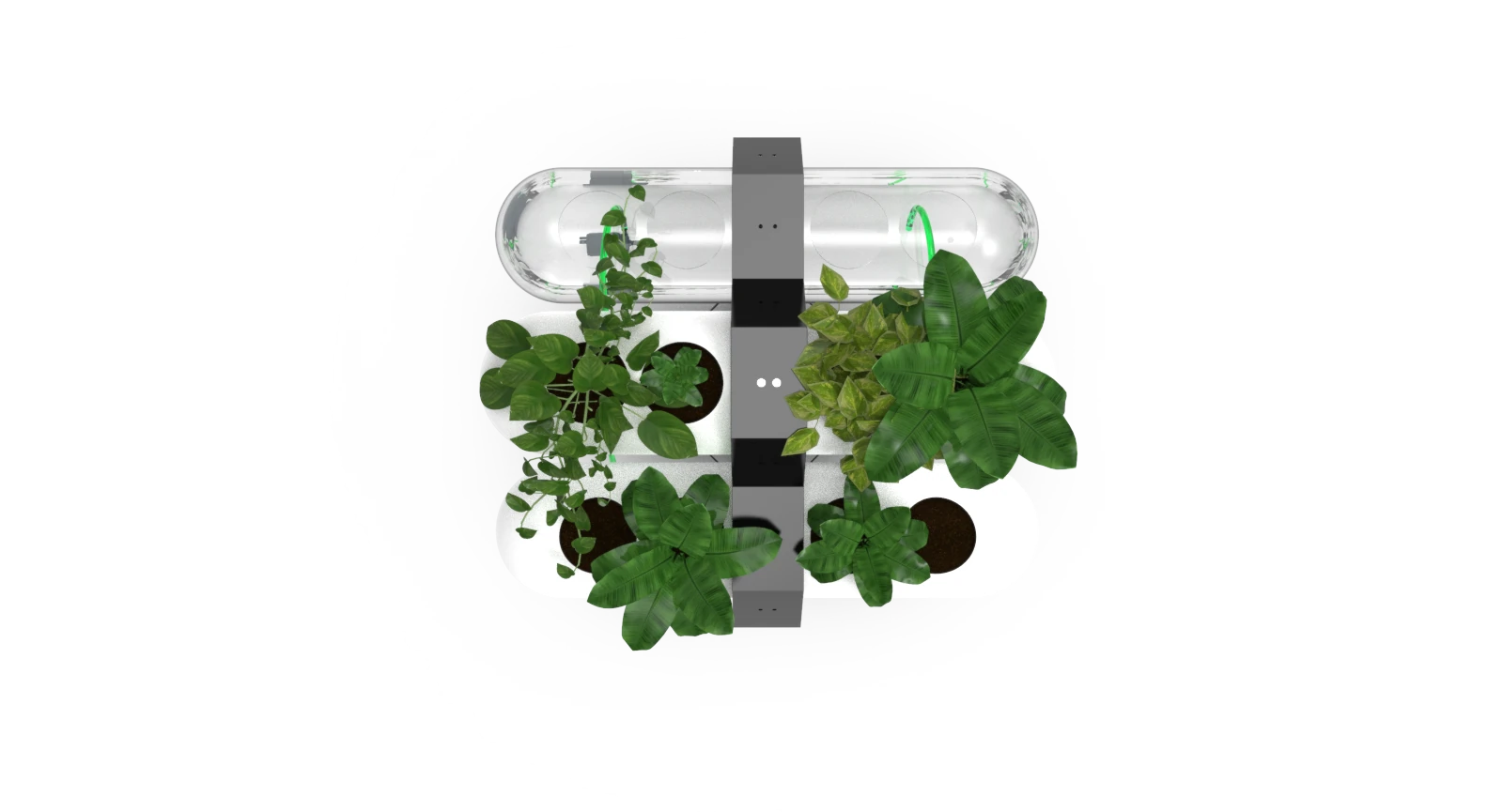
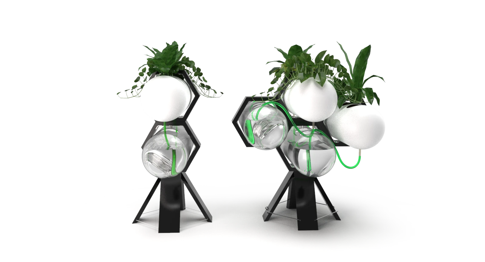
The whole thing is run by an onboard processing unit with an array of sensors that drive the pumps and heaters and keep the system alive on as little energy as possible.
How it works
In the design book of 2013 the idea is an aquarium used as the organic filter of a hydroponic bed. That makes a closed ecosystem the user can eat from on both sides, and herbs and vegetables can grow up to six times faster than usual. Fish you could eat need about 60 litres of water, which a home in a big city does not have, so the aquarium here is not for eating fish. Its extra use is making food.
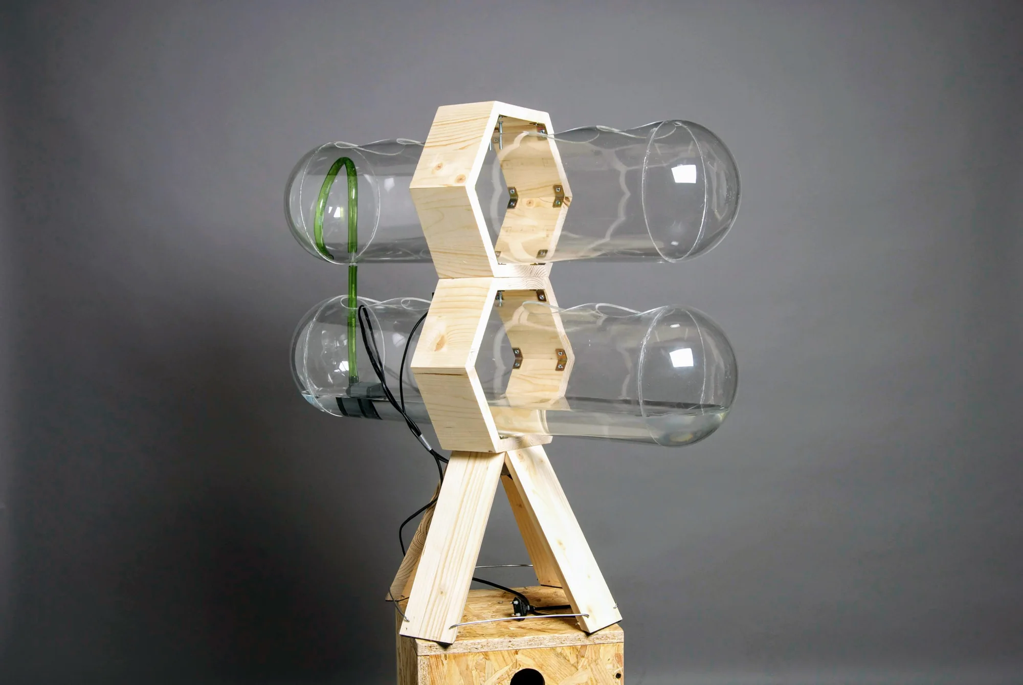
One module is two pods, one over the other, in a hexagonal pine frame. The lower pod is the aquarium. The upper pod is the growing bed, filled with coconut coir, and the plants grow out of the openings along its top.
The design book describes the water loop in a few lines. A pump in the aquarium sends the water up to the bed, and it falls back to the lower container. A floating level sensor switches the power to the pump, and the pump has a passive filter so that no solids reach the bed. An Arduino controller is offered as an extra, to handle water level, temperature and light. The aquarium needs topping up once a week.
The CAD model has the pods, the frame, the pumps, four hoses, four pipes and a bare Arduino board for the controller. It has no coir, no water, no sensors, no cables and no heater, and the book draws no heater either, although the book offers a controller to handle temperature. In 2026 the missing parts were designed to match, and the section below shows how the water enters and leaves the bed, how the aquarium is kept warm, what stops the pump and the heater when the water is low, how the cables leave the pod and what powers it all. Each part says whether it comes from the book, from the CAD or from that 2026 design.
The 2026 plumbing and electronics were designed with two AI agents, Claude and Codex, which wrote the Blender scripts. I set the design and checked every part against the book and the CAD.
The water loop
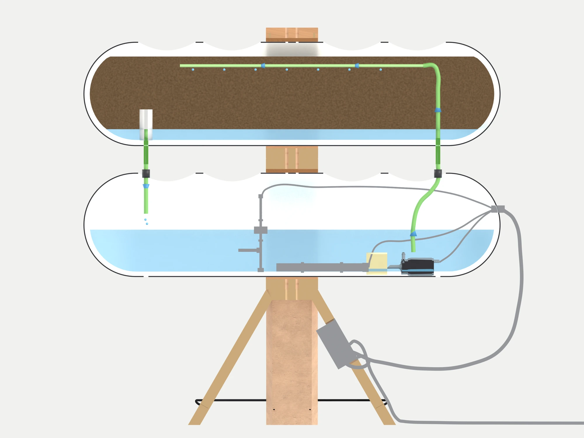
The pump lifts water from the aquarium up a hose to the end of the bed and along a drip line. It trickles down through the coir and collects in a thin layer at the bottom. The standpipe sets the depth of that layer, and the rest spills down a pipe and falls back into the aquarium. It keeps going for as long as the float switch allows. Choose a part to see what it does and where it comes from.
- Water: Growing bed. The upper pod, filled with coconut coir to just under the openings. The plants root in it and grow out through the openings along the top of the pod. About 17 litres of coir, as drawn Design book, p. 29
- Water: Drip line. The supply hose rises through the coir at the pump end and turns into a perforated tube that runs along the bed just under the surface. Water leaves it every 60 mm, so the whole length of the bed is watered. The book draws the hose rising into the bed and goes no further. Tube Ø6 mm, a hole every 60 mm Designed in 2026
- Water: Supply hose. Takes the water from the pump to the bed. It leaves the water pod through a rubber grommet in the top of the pod and meets the pipe between the pods. Hose Ø8 mm Design book, p. 29 (the hose); route designed in 2026
- Water: Pipe between the pods. A short rigid pipe through the floor of the bed. The supply hose joins it from below and the riser hose carries on from its top into the coir. A second one at the other end of the module takes the water back. Ø9 × 50 mm CAD model: feed_pipe_2 and feed_pipe_1
- Water: Water layer in the bed. The water that has run through the coir collects in a thin layer at the bottom of the bed, as the book draws it. The standpipe sets how deep the layer can get, so the coir above it never sits in water. About 22 mm deep, about 1 litre Design book, p. 43 (the layer); depth set by the standpipe, designed in 2026
- Water: Standpipe and strainer. The overflow. Water rises in the bed until it reaches the top of the standpipe, then spills into it and goes down the pipe below. A slotted sleeve around it keeps the coir out. Standpipe Ø9 mm, 22 mm above the bed floor; sleeve Ø25 mm Designed in 2026
- Water: Return pipe. Carries the overflow out of the bed, through a grommet in the top of the water pod and down. It ends about 30 mm above the water, so the water falls through air and lands on the surface, which puts air back into it. Ø8 mm Designed in 2026; the book only says the water falls back to the lower container, p. 42
- Water: Aquarium. The lower pod holds the water and the fish. Water leaves the loop by evaporation and through the plants, so the book says to add water to the aquarium every week. About 8 litres, drawn to just under half Design book, p. 29 and p. 42
- Water: Pump. A small submersible pump on the floor of the water pod, at one end, running for as long as the float switch allows. The drain can pass about 70 litres an hour through a 7 mm bore, so the pump is chosen to give about half that. 12 V, about 4 W, 30 to 40 L/h CAD model: pump_2; rating designed in 2026
- Water: Pre-filter. A foam sleeve on the pump's inlet. The book says the pump has a passive filter that keeps solid objects from reaching the bed; this is one way to make it, and it can be taken off and rinsed. Ø43 × 40 mm Design book, p. 42 (the filter); its form designed in 2026
- Heat and power: Pump. Runs from the same 12 V as everything else. Its lead leaves the water pod with the others, through the gland. 12 V, about 4 W CAD model: pump_2; rating designed in 2026
- Heat and power: Heater. A sealed 12 V heater on the floor of the water pod, in the water's path from the return pipe to the pump. Its element is the kind whose resistance rises as it warms, so it levels off by itself. The controller switches it to hold the setpoint. Lying in the lowest curve of the pod, it stays covered until the float switch cuts it. 25 W for about 8 litres, about 3 W per litre, which by the usual rule of thumb holds the water 6 to 10 °C above the room Designed in 2026; the book has the controller handling temperature, p. 35, and draws no heater
- Heat and power: Float switch. A float on a post, riding on the surface between two stops. When the water has fallen about 10 mm the float reaches the lower stop and the switch opens. It is in series with the 12 V feed to the pump and the heater, ahead of the controller, so neither runs dry even if the controller fails. Opens about 10 mm below the working level Design book, p. 29 and p. 42 (the switch on the pump's supply); its place and the heater interlock designed in 2026
- Heat and power: Temperature probe. A waterproof digital probe clipped to the float post, 40 mm below the surface and clear of the heater, so it reads the water and not the element. The controller reads it and switches the heater. Ø6 × 36 mm Designed in 2026; the book has the controller handling temperature, p. 35, and names no sensor
- Heat and power: Cable gland. The cables from the pump, the heater and the post leave the water pod together through one sealed gland in the end of the pod, above the waterline, and carry on as one multicore cable. Nothing passes through the pod below the water. Gland Ø14 mm Designed in 2026
- Heat and power: Drip loop. The pump cable plugs into the faceplate from below and leaves in a J, so water running down it drips off at the lowest point and does not run into the connector. It then climbs the leg under two clips and runs under the water pod to its gland. Designed in 2026
- Heat and power: Controller and supply. The controller and the 12 V supply are one module, set into a window cut through the front leg. The leg is a 20 mm plywood plate, so the module's faceplate lies level with the leg's face and its body passes through and stands behind it. The faceplate has a status light and the two connectors. The book calls the Arduino optional and puts it in the premium pack, to handle water level, temperature and light, and its technical drawing marks this place for it. Here it reads the probe and switches the heater through a transistor. Faceplate 62 × 92 mm, body 40 mm deep Design book, p. 35 and p. 53 (the place); the module and its job designed in 2026, the CAD has a bare board
- Heat and power: Mains inlet. The supply is inside the module, so no adapter hangs on the cord. The white mains cord plugs straight into the leg: its moulded plug flows into the cord, which runs down the face of the leg under two clips and away along the floor. The supply is the only part at mains voltage; everything in the pods runs at 12 V. The pump takes about 4 W, the heater 25 W and the controller about 1 W, so 36 W is enough. 12 V, 3 A Design book, p. 35 and p. 42 (one supply); its place in the leg and its rating designed in 2026
- Across the pods: Growing bed. The upper pod in section: a round wall around the coir, with the water layer in the curve at the bottom. Design book, p. 29
- Across the pods: Drip line. The drip line cut across, a little under the surface of the coir. A drop is falling from one of its holes. Designed in 2026
- Across the pods: Aquarium. The lower pod in section, with the water below its middle. Design book, p. 29
- Across the pods: Float switch. The float post stands just behind the cut, with its float on the surface between two stops and the temperature probe pointing off to one side below it. Designed in 2026
- Across the pods: Heater. The heater cut across, lying in the lowest curve of the pod. It stays covered until the float switch cuts the power. Designed in 2026
- Across the pods: Wooden cradle. Each hexagon is solid pine round a round bore, so the wood meets the whole pod instead of touching it at six points. 100 mm deep Designed in 2026
- Across the pods: Legs. The two legs and the wire stretcher at their base. CAD model
- Supply end: Pump. The pump seen end-on, on the floor of the water pod at the supply end. The foam pre-filter is behind it. CAD model: pump_2
- Supply end: Supply hose. Rises from the pump, bends to the end of the pod and goes up through a rubber grommet in its top. Design book, p. 29; route designed in 2026
- Supply end: Grommet. A rubber ring seals the hole where the hose leaves the water pod. There is another at the return pipe. Ø15 mm Designed in 2026
- Supply end: Pipe between the pods. The pipe through the floor of the bed, cut lengthwise. The hose joins it from below. Ø9 × 50 mm CAD model: feed_pipe_2
- Supply end: Riser and drip line. From the top of the pipe the hose climbs through the coir. At the top it turns and the drip line leaves the cut here, running away along the bed. Hose Ø8 mm Designed in 2026
- Supply end: Growing bed. The coir, and the water layer in the bottom of the pod. Design book, p. 29
- Supply end: Aquarium. The water in the lower pod. Design book, p. 29
- Drain end: Standpipe and strainer. The standpipe stands 22 mm above the floor of the bed, inside a slotted sleeve. The water layer cannot get deeper than its top. Sleeve Ø25 mm Designed in 2026
- Drain end: Water layer in the bed. The layer at the bottom of the bed, as deep as the standpipe is tall. About 22 mm Design book, p. 43; depth designed in 2026
- Drain end: Pipe between the pods. The second pipe through the floor of the bed. The overflow goes down it. Ø9 × 50 mm CAD model: feed_pipe_1
- Drain end: Return pipe. Goes on down through a rubber grommet in the top of the water pod and stops about 30 mm above the water. Ø8 mm Designed in 2026
- Drain end: Falling water. The overflow drops from the end of the pipe onto the surface, which puts air back into the water. Designed in 2026
- Drain end: Aquarium. The water in the lower pod, seen from the drain end. Design book, p. 29
From the design book, 2013
- Height to the top of the second module
- about 70 cm
- Weight, structure only
- 5 kg
- Weight with the coir, the water and the components
- 20 kg
The figures in the next table are chosen, or worked out from the sizes in the CAD model. None was measured on a built unit.
Worked out in 2026
- Water in the aquarium, as drawn
- about 8 litres
- Coir in the bed, as drawn
- about 17 litres
- Pump
- 12 V, about 4 W, 30 to 40 L/h
- What the drain passes
- about 70 L/h, for a 7 mm bore and 40 mm of head
- Heater
- 25 W, about 3 W per litre
- Power supply, built into the leg
- 12 V, 3 A; about 30 W with the heater on
The model, rebuilt in 2026
The CAD model survived as SolidWorks files, and as a Blender scene made from them in 2023. In 2026 that scene was cleaned up. Every part is named and set at its real size, the screw threads are simplified, and the lighting is a studio set built for it.
The pods sat loose in thin hexagonal rings, with 15 mm of play at the flats and more at the corners, so each ring now has a pine cradle with a round bore that closes round the whole pod.
The plumbing and the electronics were redrawn. In the CAD the hoses ran loose over the pods and ended in the planting openings, four short pipes stood under the pods as stubs for them, and the controller was a bare Arduino board. Now each connection is one white silicone hose, moulded with a soft flared end on the dome of each pod it joins, so that the hose runs straight on into its fitting. The stubs are gone. The controller and the power supply are one module set flush into a window in the front leg: the white mains cord plugs straight into its face, with the pump cable beside it, both in white sleeving held by small clips. None of this is in the CAD or in the book.
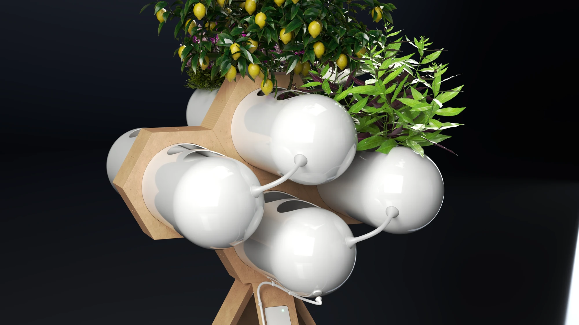
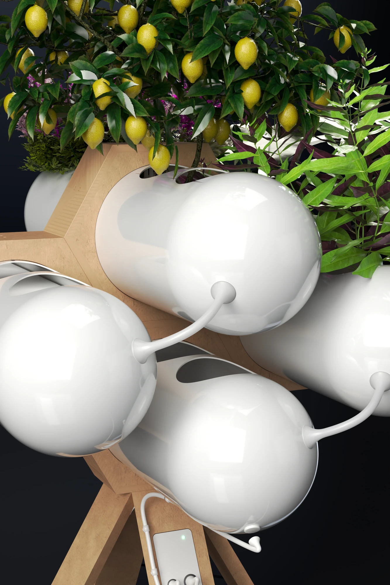
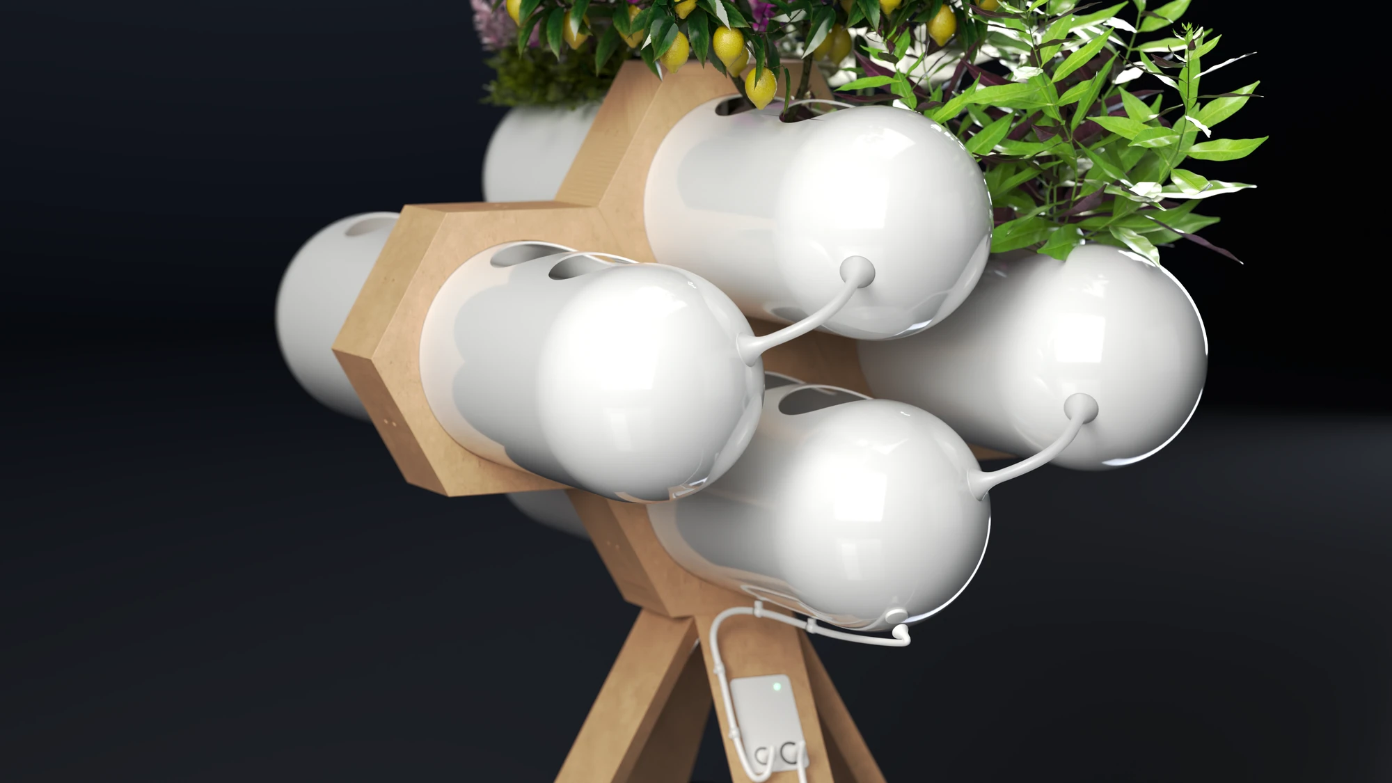
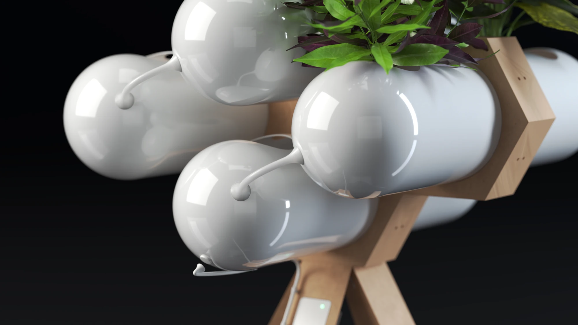
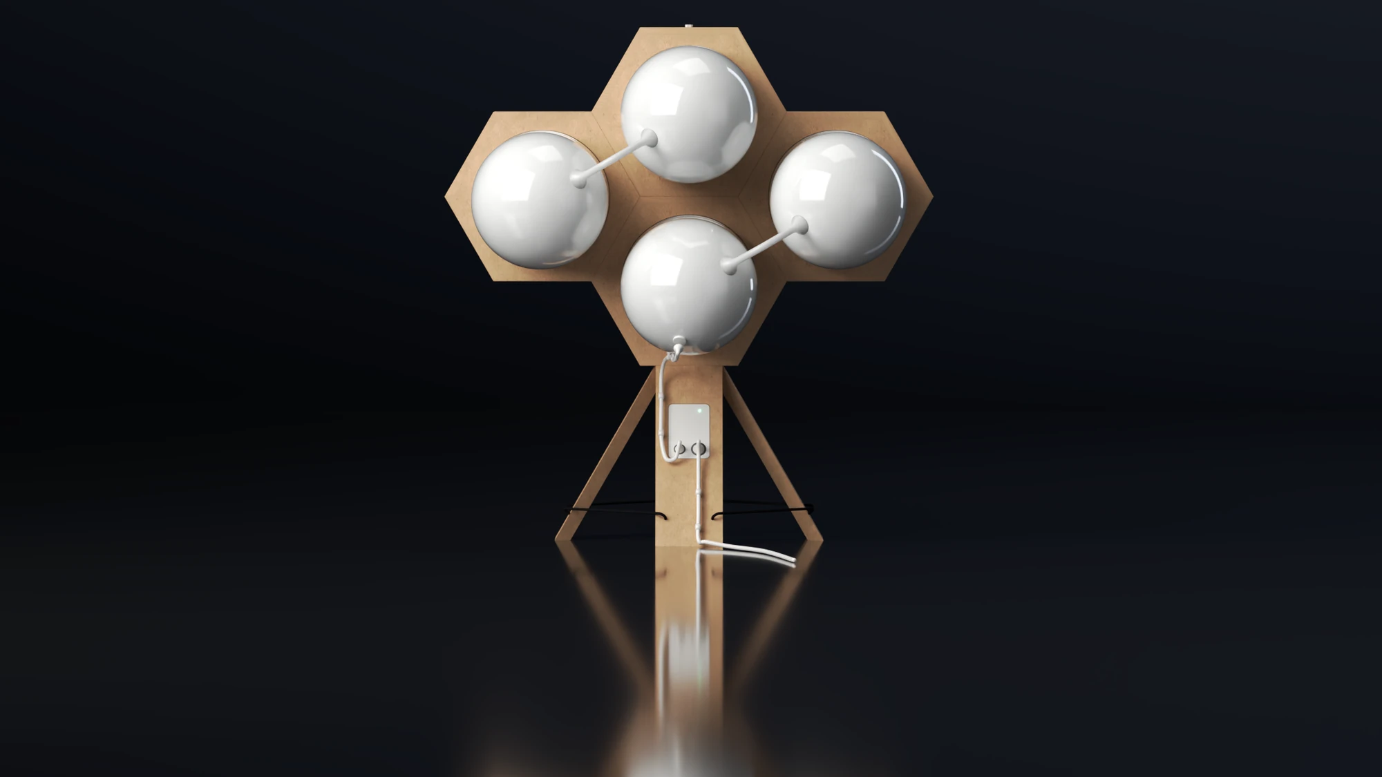
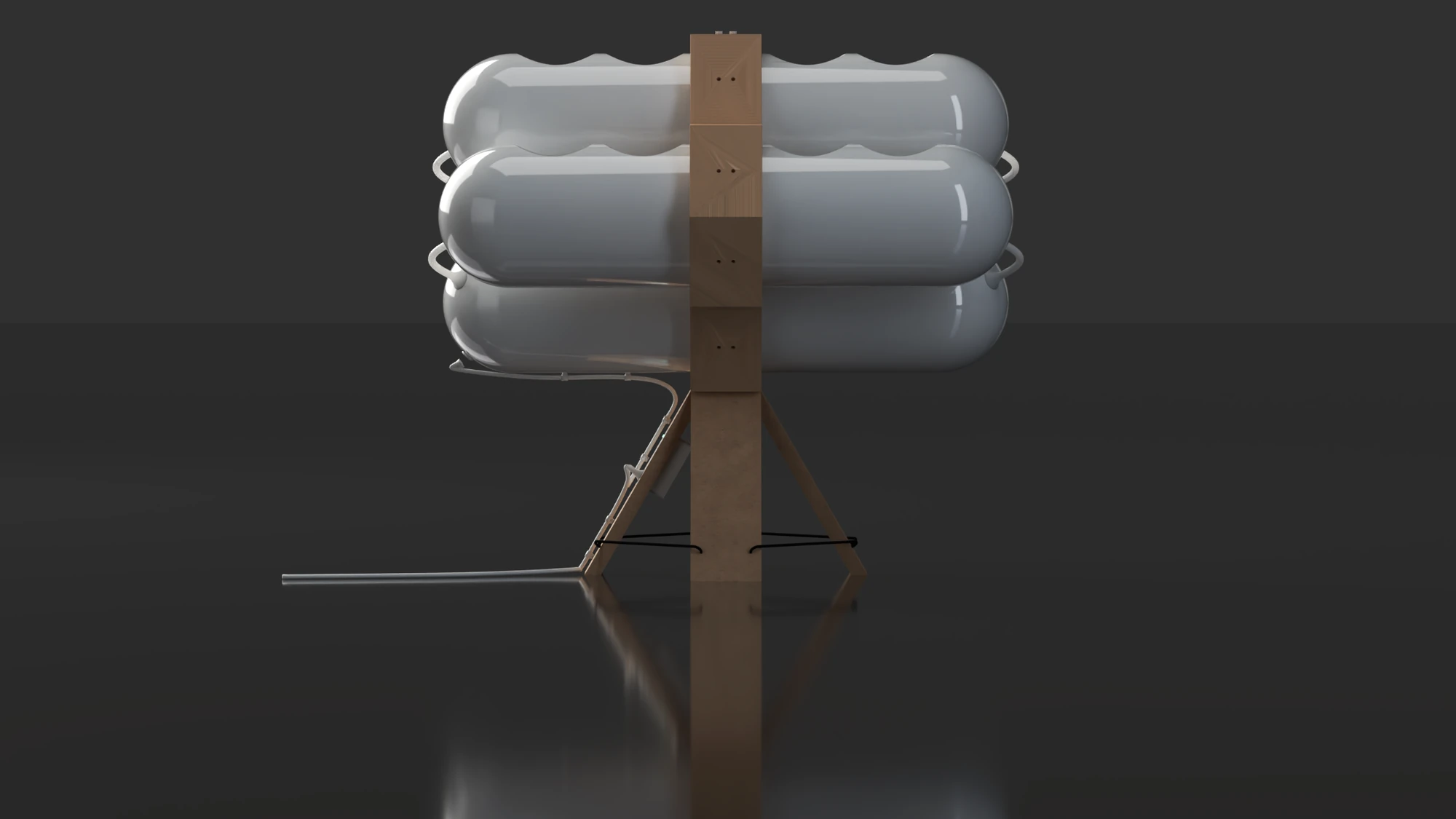
There are 29 parts in six groups: four pods, the pine frame with its four cradles, two legs with their wire stretchers, four hoses, two pumps with the controller module, its cords and their clips, and the fasteners. In the viewer each group can be shown alone, and the model can be taken apart and measured.
Loading the model
The whole assembly
Drag to turn it. Pinch, or hold Ctrl or Cmd and scroll, to zoom. Choose a group to see it alone.
The CAD data does not say what the pods are made of, so the viewer lists their material as not specified. The design book says they are acrylic, made by a plastics workshop near Milan and welded. The pumps are models that came with the original CAD files; the controller module and the window cut for it in the leg are a 2026 design.
The model was checked against the engineering drawing that came with it. The drawing shows the two-cell desktop version and the model is the four-cell one, so the overall footprint cannot be compared; the pod, the cell and the height can.
Model against the drawing
- Pod, diameter and length
- 200 × 800 mm, drawing 200 × 800
- Hexagonal cell, flat to flat
- 251.1 mm, drawing 251
- Height
- 766.0 mm, drawing 766.1
In a room
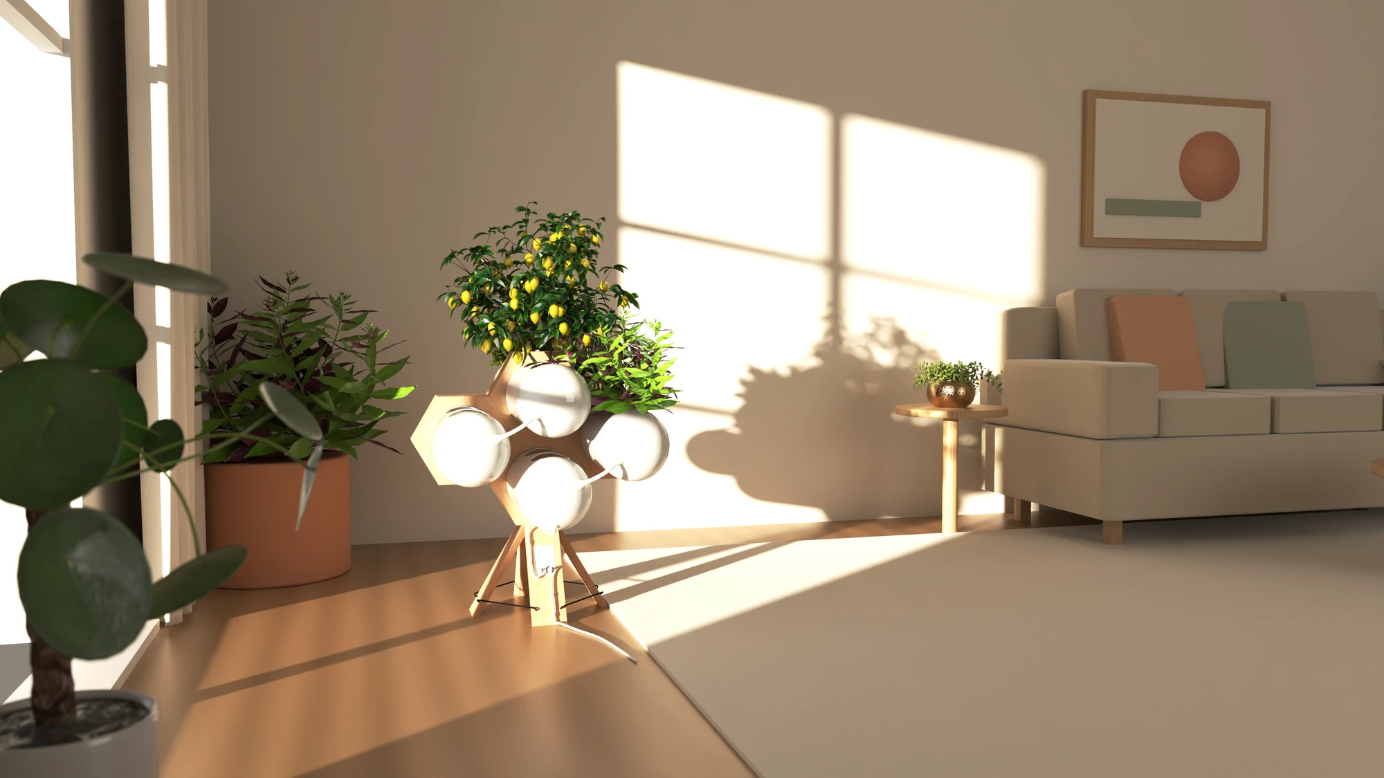
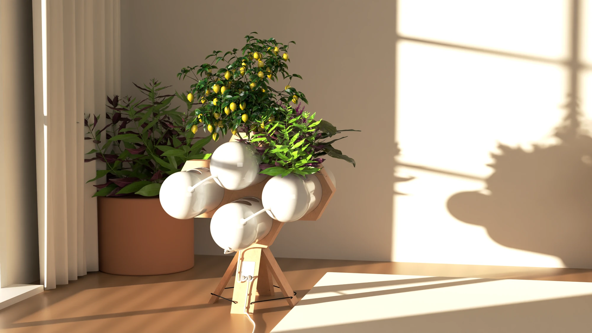
The room is built for the render, in low sun. The plants around the device are the same plants as on it, scaled up and potted.
Design studies
Branding design
Prototype