Spiro
How a delivery study became two aircraft
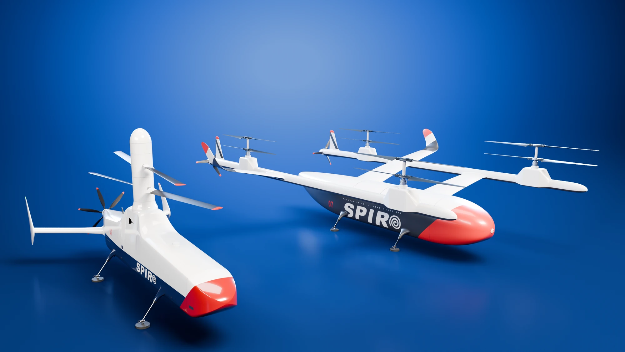
Spiro is an unmanned aircraft that lands to deliver parcels. I first drew it in 2017, and when I returned to it in 2026 I asked which aircraft could carry a 25 kg parcel best. The answer depended on how a failure is judged. A strict reading favours a VTOL, a winged aircraft that takes off and lands vertically. A looser reading favours a coaxial helicopter, which has two rotors turning in opposite directions on one mast, and I developed both aircraft.
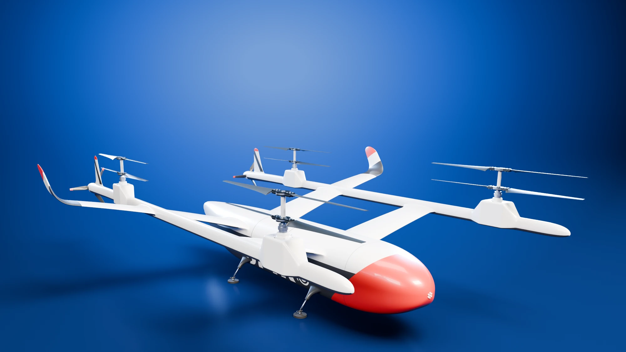
The VTOL
- Size
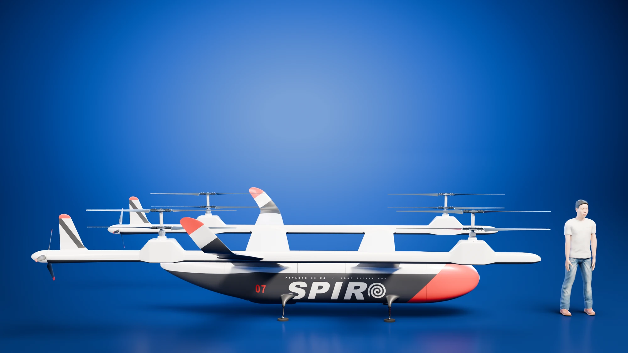
- 5.8 m wide, 6.9 m long and 1.75 m high
- Lift
- Eight electric rotors of 2.0 m diameter, in four pairs
- Cruise
- Two pusher propellers, 129 km/h at best range
- Cargo
- Totes on a tray that slides out through a door at either end
- Take-off mass
- 252 kg at a 100 km delivery radius with 25 kg of cargo
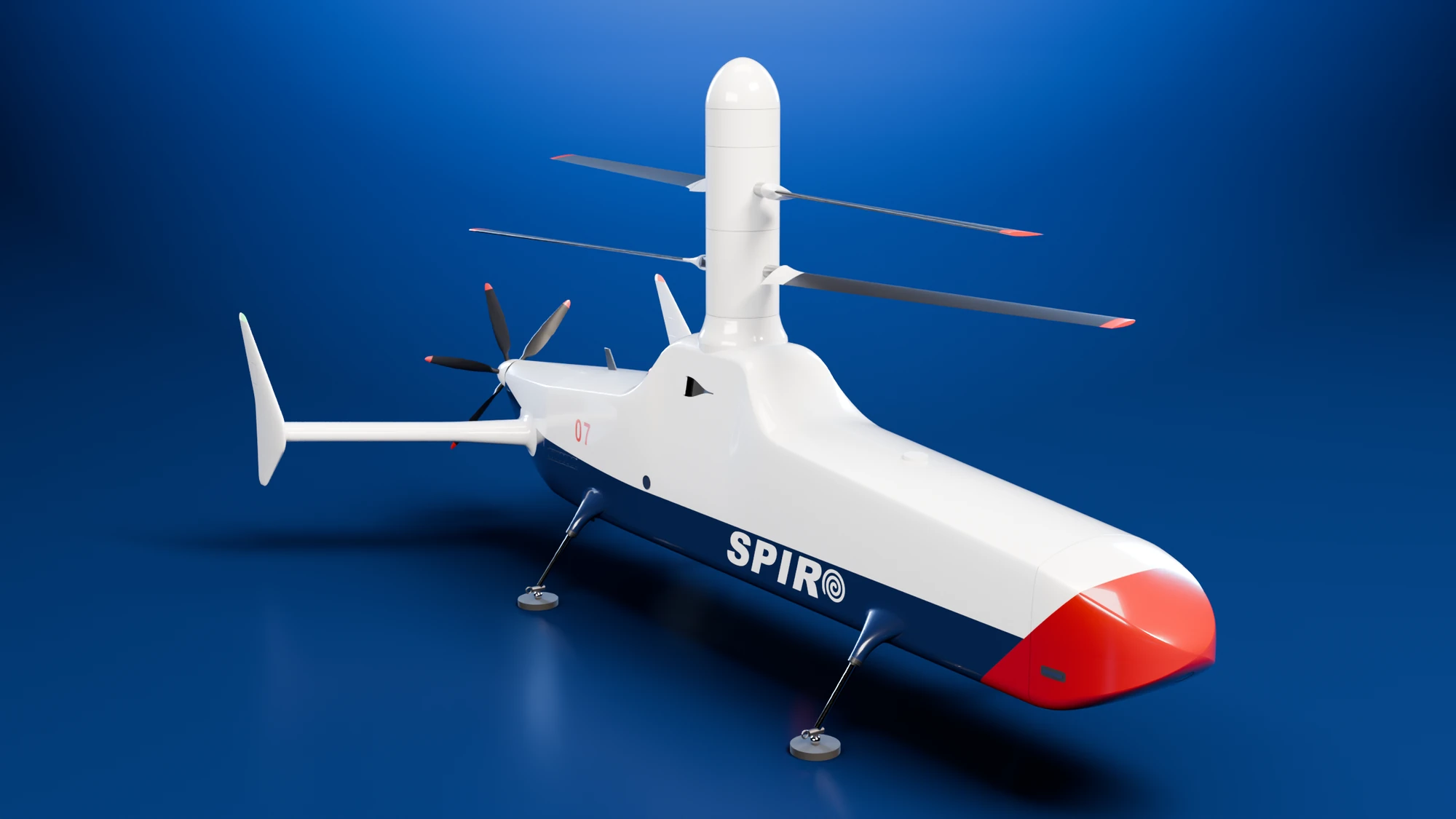
The helicopter
- Size
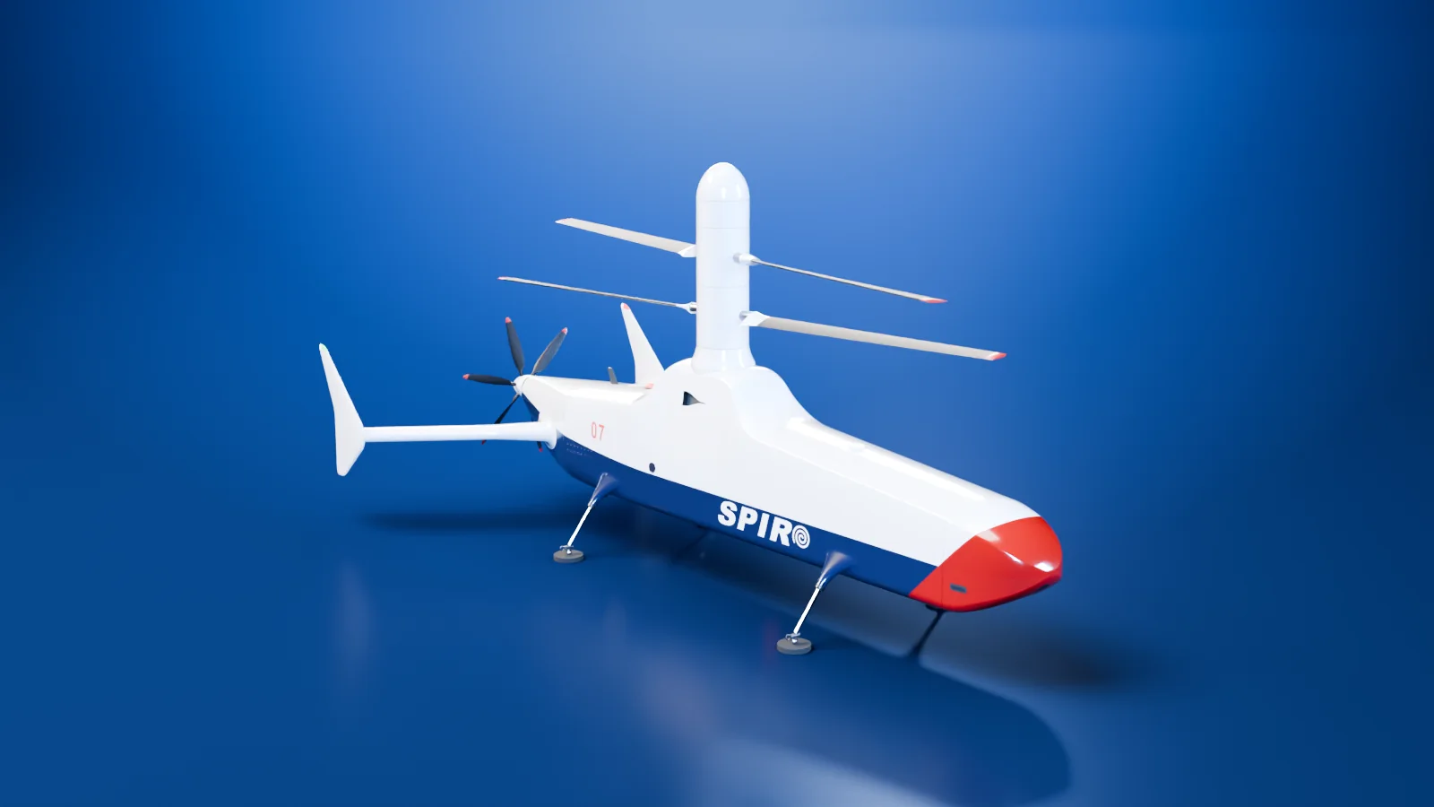
- 3.96 m long to the spinner, 4.77 m with the tail
- Lift
- Two coaxial rotors of 1.7 m radius, two blades each
- Cruise
- A six-blade pusher propeller of 0.88 m diameter
- Cargo
- Three totes, loaded through a door in the nose
- Take-off mass
- 212 kg with one 44.7 kW engine, 246 kg with two 28.3 kW engines, at a 100 km delivery radius with 25 kg of cargo
What Spiro delivers
Spiro carries 25 kg of parcels in totes of 0.60 × 0.40 × 0.30 m. It lands to deliver, with no winch, swaps the parcel for a return one and flies back. The study covers deliveries 5, 20, 50 and 100 km away, with up to five minutes of hover reserve, at 40 degrees Celsius at sea level.
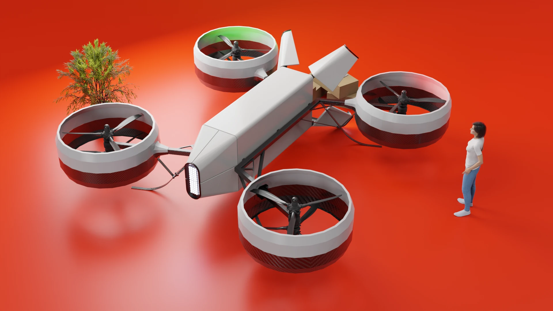
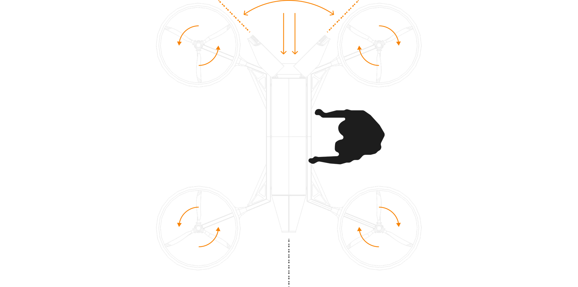
The 2017 version was a rectangular fuselage with four ducted rotors on arms and a door at each end for loading. Loading at both ends is the one idea from 2017 that the VTOL keeps.
Why the study produced two aircraft
I compared aircraft with separate lift and cruise systems against helicopters, and I wrote the comparison rules before I read any results. One rule decided which kind of aircraft could enter the ranking. After losing one lift unit or its engine, the aircraft must land under control and hold its heading.
A VTOL can meet the rule by sending the lost thrust to its other rotors. A helicopter cannot, because its shared rotor system and gearbox are single points of failure. A helicopter does enter the ranking if it is credited with autorotation.
In autorotation the engine is off and the rotors keep turning freely while the helicopter glides down onto a cleared strip, which I assumed to be about 60 m by 20 m. Autorotation covers the loss of the engine. It does not cover a failure of the rotor system.
With autorotation credited, the helicopter comes out about a third lighter than the VTOL.
Take-off mass at a 100 km delivery radius. Each bar covers the middle 90 percent of the results from repeated calculations with uncertain inputs, and the mark is the median, where half the results are lighter and half heavier.
kg
I do not know which reading of the rule is right, so I developed both aircraft. The helicopter's autorotation is an assumption in the study.
The VTOL
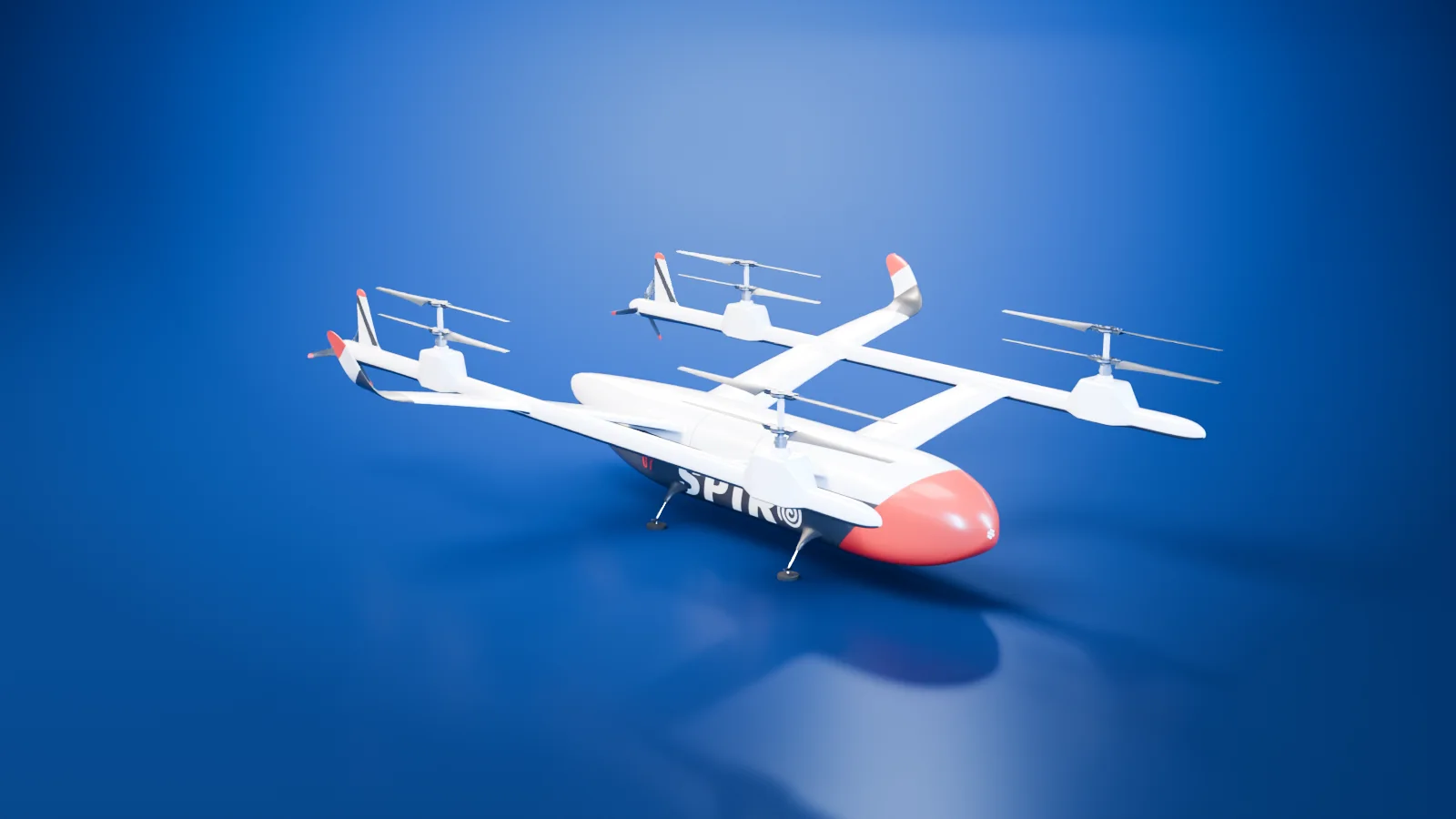
The VTOL has two wings in tandem on twin booms, around a hull with a cargo door at each end. In hover, its eight electric rotors carry it. The two rotors of a pair share one axis and turn in opposite directions.
In cruise the wings carry the weight. A pusher propeller at the end of each boom drives the aircraft forward, and the lift rotors park along the booms. A rotary engine drives the pushers through shafts and gearboxes and charges the battery. It does not run in hover.
Loading VTOL
How the VTOL is driven
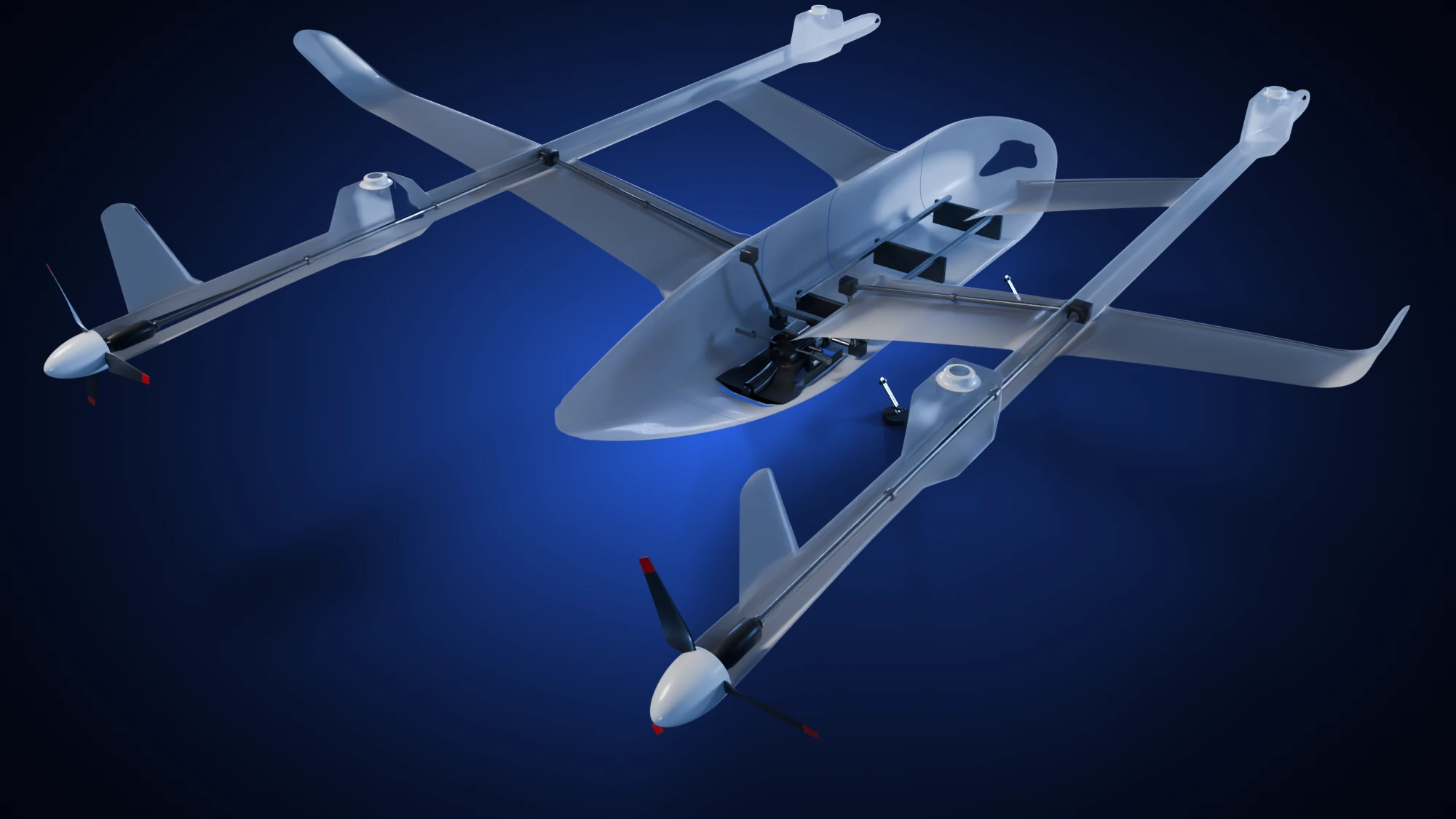
The engine sits below the cargo tray. A gearbox divides its drive between the two booms, and shafts run through the rear wing and along each boom to the pushers. The lift motors are electric and separate from the engine's drive. Choose a view and a part to follow each path.
 Engine
From the engine to the pushers
The gearbox divides the engine's drive between the two booms and their rear propellers.
Choose a part here, or tap a marker in the cutaway.
Engine
The rotary engine sits below the cargo tray, leaving the loading path above it clear.
- Mechanical drive: Engine. The rotary engine sits below the cargo tray, leaving the loading path above it clear.
- Mechanical drive: Drive gearbox. Divides the engine's drive between the left and right sides.
- Mechanical drive: Wing shaft. Carries the drive across the rear wing to the boom.
- Mechanical drive: Boom shaft. Runs aft inside the boom toward the pusher propeller.
- Mechanical drive: Pusher bearing housing. Supports the shaft at the end of the boom, just ahead of the propeller.
- Power and fuel: Battery. Supplies electric lift during hover.
- Power and fuel: Wing fuel cell. Carries fuel for the engine used in cruise.
- Power and fuel: Power cables. Carry power out to the lift stations.
- Power and fuel: Voltage converter. Supplies the lower-voltage onboard electronics.
- Lift motors: Lift motors. Two independent annular motors drive the concentric shafts, one motor for each rotor.
- Lift motors: Boom shaft. This separate mechanical shaft carries engine power aft to the pusher.
- Lift motors: Motor controllers. The controllers supply the lift motors from the high-voltage battery.
- Lift motors: Hanger bearing. Supports the long mechanical shaft inside the boom.
Loading a parcel
Both cargo doors open to 100 degrees and the tray slides 1.45 m out of the hull. A parcel leaves, its replacement enters, and the tray retracts.
What a virtual wind tunnel showed
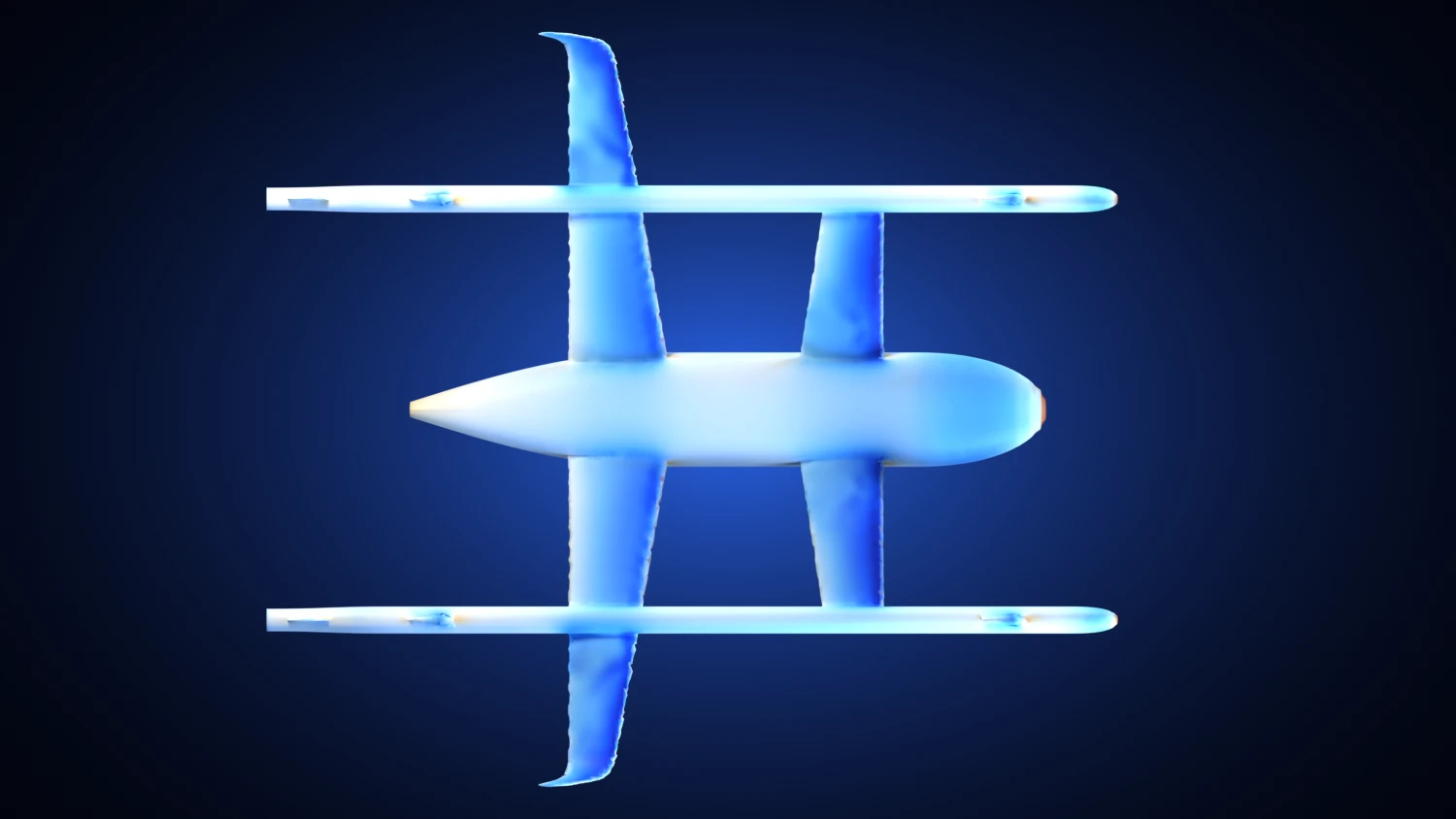
I put my first 2026 airframe, a tandem-wing aircraft with eight rotors on twin booms, in a virtual wind tunnel. The method is computational fluid dynamics, which calculates how air flows around a shape and the forces it produces.
The booms add 22 percent of the drag and only 8 percent of the lift.
Each part's share of the lift and of the drag on the first airframe at 6 degrees.
Share of the lift
Share of the drag
| Part | Share of the lift, percent | Share of the drag, percent |
|---|---|---|
| Wings | 75.2 | 57.3 |
| Hull | 15.3 | 19.2 |
| Booms | 8 | 21.8 |
| Blends | 1.4 | 1.1 |
| Fins | 0 | 0.7 |
The next figure shows the same run in more detail, starting with where the air pushes on the skin.
 Nose
Where the pressure is
Pressure on the skin, seen from above, at 6 degrees and 30.7 m/s. Blue is suction, red is air pushed against the aircraft.
Choose a part here, or tap a marker in the cutaway.
Nose
The air is stopped here, so the pressure is highest.
- Pressure: Nose. The air is stopped here, so the pressure is highest.
- Pressure: Strongest suction. On the outer wing, where the lift is made.
- Pressure: Wing tops. The pressure above the wing is lower than the air around it, and that difference is the lift.
- Hull air: Nose. The air stops at the nose and splits (blue).
- Hull air: Over the hull. The air speeds up over the hull (yellow).
- Hull air: Behind the tail. Slow air is left behind the tail (blue).
- Boom air: Between the masts. The air speeds up over the boom between the rotor masts (yellow).
- Boom air: Behind the tail. Slow air is left behind the tail (blue).
- Wake: Booms. The two long booms leave deep wakes: the air is slowed by 14 percent.
- Wake: Hull and wing roots. Behind the hull and the root of the wings the air is slowed by 16 percent.
- Wake: Outer wing and winglet. Behind the outer wing and the winglet the air is slowed by 3 percent.
The helicopter
The helicopter has no wing. Its two rotors turn in opposite directions on one mast, over a short, steep hump. A pusher propeller at the rear drives it forward in cruise, turned by an engine behind the cargo bay.
Loading Helicopter
Paint studies
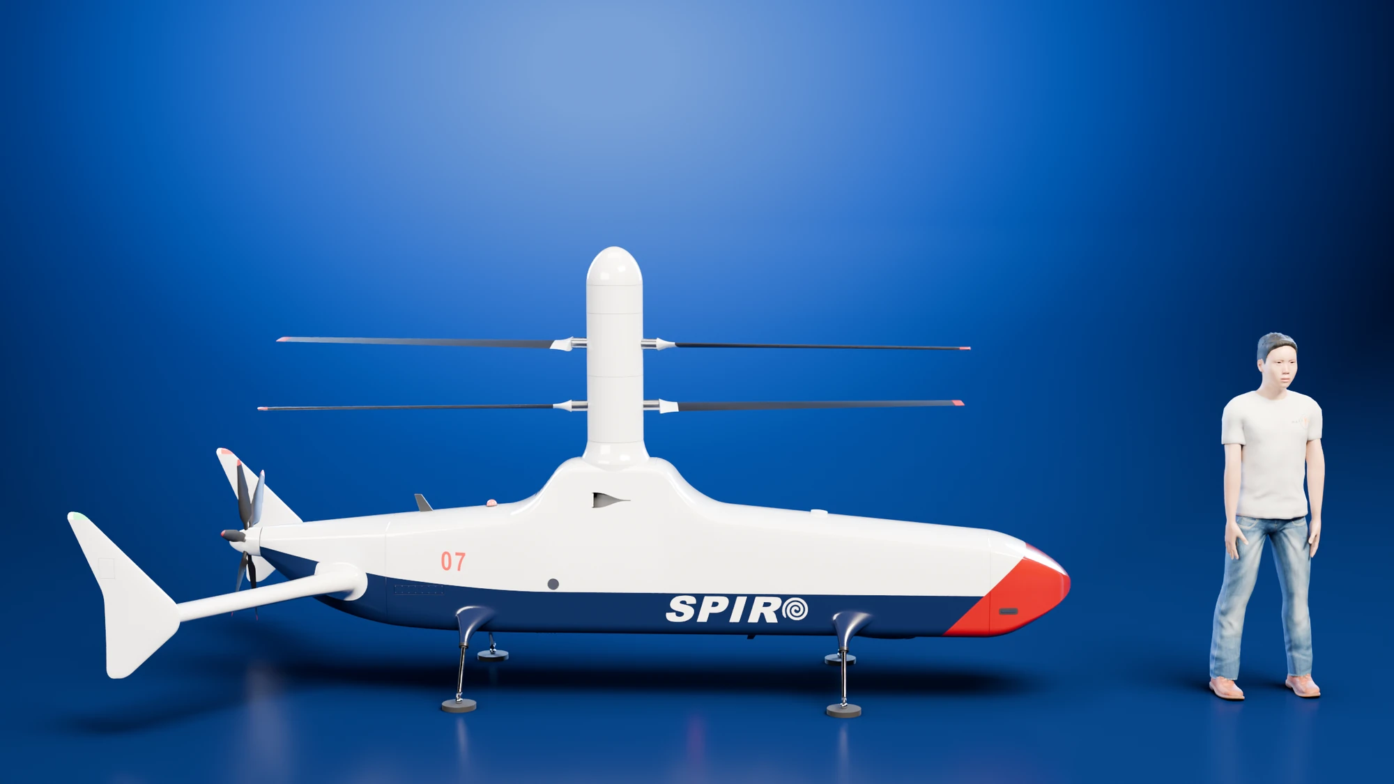
The helicopter also exists in three military paints: matt grey, light grey and camouflage. The airframe is the same, and no weapon or sensor is added.
How the helicopter steers
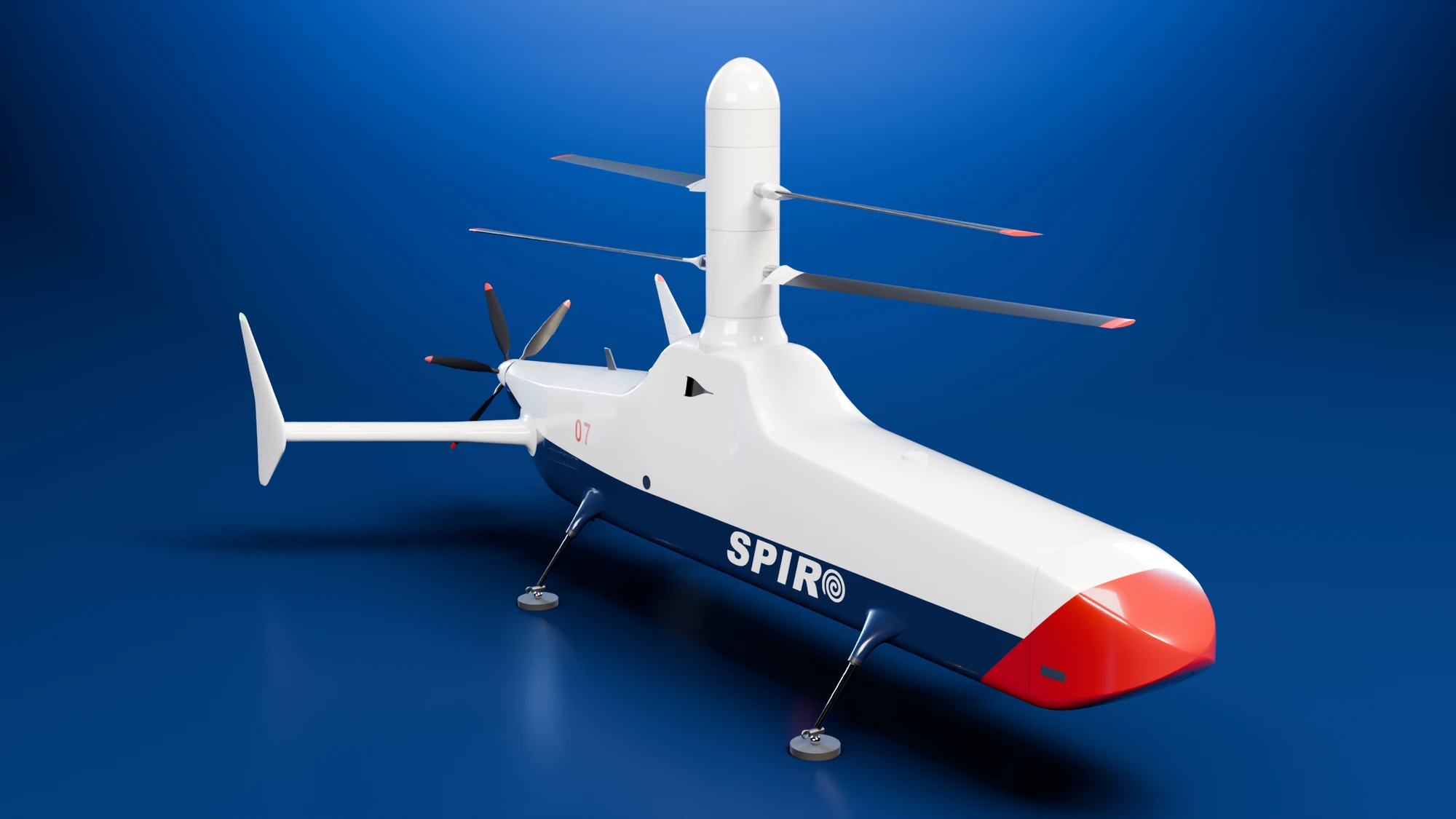
A helicopter steers by changing the pitch of its blades, which is the angle each blade makes with the air. A swashplate changes the pitch. It is a pair of rings round the mast, one fixed and one turning with the rotor. Raising the rings changes the pitch of every blade at once, which changes the total lift. Tilting them makes each blade's pitch rise and fall once per turn, which tilts the rotor and moves the helicopter sideways.
The two rotors turn in opposite directions, which cancels the twist that would turn the body. Giving one rotor more pitch than the other turns the nose. The head has two swashplates, one for each rotor. Three servos on top of the gearbox move the lower one, and rods and levers carry the motion up between the rotors to the upper one.
Coaxial rotor head
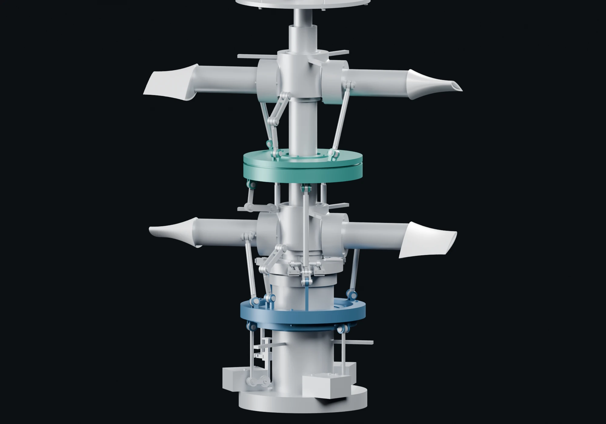
Rotor-head cutaway. Interactive assembly loads when in view.
The emergency parachute
The helicopter carries an emergency parachute. A pack in the body would send its lines through the two rotor discs, so I put the pod above the upper rotor, with the attachment on the mast axis. The helicopter then hangs nearly level in the four loading states I studied. I modelled a stationary support through the concentric shafts, with a keyed gearbox foot, a seated pod deck and a pinned bridle receiver. The mounting and sampled clearances are checked geometrically; deployment loads and the attachment into the airframe remain unresolved.
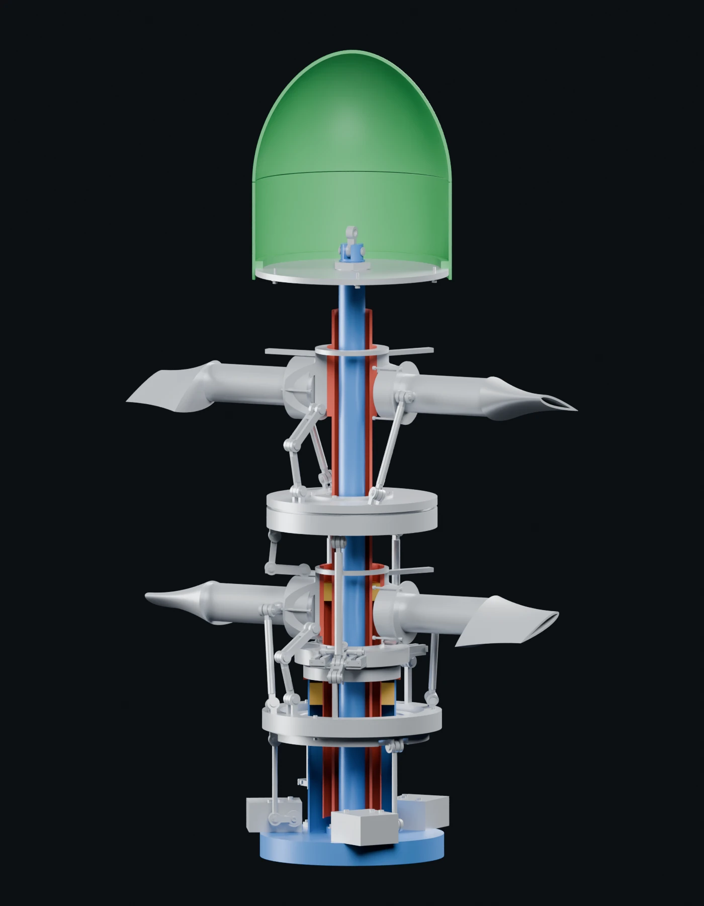 Pod enclosure
The current head
The pod deck and bridle receiver are supported by a continuous stationary post, fixed to the gearbox case.
Choose a part here, or tap a marker in the cutaway.
Pod enclosure
The current crown sits above both rotors. Six screws attach its integral seating ledge to the removable deck. The canopy pack, lid release and launcher remain unresolved.
- Current head: Pod enclosure. The current crown sits above both rotors. Six screws attach its integral seating ledge to the removable deck. The canopy pack, lid release and launcher remain unresolved.
- Current head: Pinned bridle attachment. A retained shoulder pin joins the bridle receiver to the stationary support. The pod deck seats on an integral shoulder below it, retained by a threaded nut and locking washer. Nominal installation paths and ±15° bridle articulation pass geometric checks; opening-load capacity is not established.
- Current head: Concentric drive shafts. The red inner and outer shafts are the actual rotor-head geometry. Their front halves are hidden in this render to expose the nested arrangement and blue stationary mounting post.
- Current head: Stationary sleeve. The blue sleeve supports the rotor-head assembly. Its geometry is current; bearing duty, strength and the parachute load path still need engineering.
- Current head: Gearbox interface. A piloted, keyed foot and four retained screws connect the stationary support to the gearbox top. The gearbox internals, its attachment into the body and opening-load capacity remain unresolved.
I simulated the opening for a design point of 202 kg and a 10.69 m canopy sized to descend at 7 m/s. Opening at 52 m/s gives a peak pull of about 10 kN. Slowing to 25 m/s first reduces the pull to about 3.7 kN, but the helicopter loses more height before it settles, 56 m against 39 m. Opened from a hover, it loses about 78 m. These are model outputs and do not establish safe deployment heights.
Parachute opening model
Model of a 202 kg aircraft with a 10.69 m canopy and an unreefed opening. These are estimates from a calculation and have not been tested in a deployment.
- Peak pull
- 9.99 kN
- Full inflation
- 4.99 s
- Height lost to settling
- 38.6 m
- Steady descent
- 7 m/s
The force on the parachute lines
How far it has dropped since opening began
How far the body tips from level, first six seconds
A pull from high above the centre of gravity can pitch the helicopter quickly and bring the blades of the two rotors closer together. I adopted two measures. The helicopter slows to about 25 m/s before the parachute fires when there is height, and the canopy opens in a controlled way, either reefed so that it fills in stages or through a slider. The curves above are for an unreefed opening, so they do not model either measure.
Where the study stands
Aircraft mass, power and range are estimates from my models, and engine ratings come from the manufacturers' data. The VTOL's take-off mass is an earlier sizing estimate. The parachute study used a design point of 202 kg, lighter than the later helicopter estimates of 212 and 246 kg, so it needs checking again. The VTOL and the helicopter have had no flow simulation of their own, no wind-tunnel test and no flight test. The helicopter's engine and the parachute pack are open choices, and its cargo-door motion, nose packing and rotor clearances are unresolved.
The 2026 work was done with AI agents, Claude and Codex, which wrote the modelling, analysis and rendering scripts. I set the design and the questions, checked the results and rejected what did not hold.