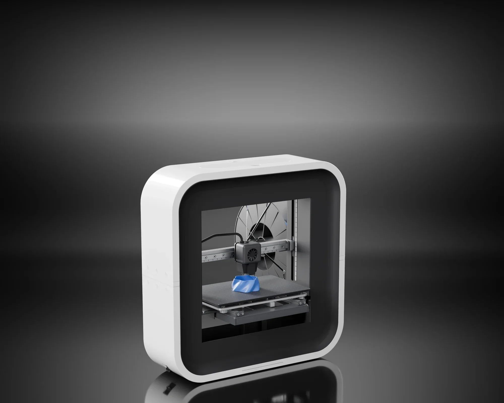
In 2011 most 3D printers had a DIY, plywood construction look. As the sole designer, in my master’s thesis, I bet on a more visually appealing design, and it was widely embraced in the industry.
- 6
- awards, 2013 to 2016
- $2,499
- in PCMag’s 2014 review
- 9.5 kg
- in the manual
- 250 mm
- square window on the print
Six awards in four years.
From Portugal’s product of the year to Make:’s rookie of the year.






“An easy-to-use, attractive, portable machine”
Make:, 2015
“Ready to go within minutes of taking it out of the box”
3D Hubs, 2016
“This was, indeed, a good looking product.”
3D Printing Industry, 2014
Not a plywood box.
In 2011, 3D printers were mostly DIY plywood constructions, built for function rather than looks. I believed a 3D printer could be a consumer electronics product, easy to use and plug-and-play, so I designed BEETHEFIRST as one.
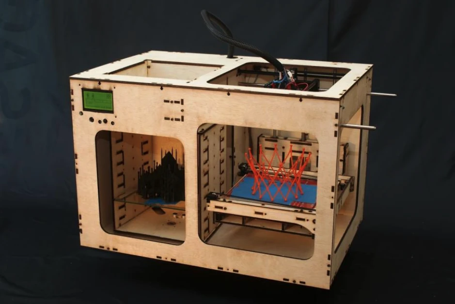
Multiprinter 2. Laser-cut plywood.
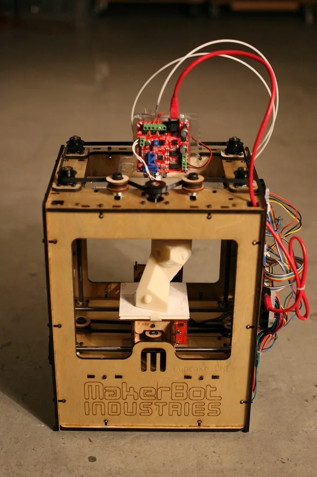
MakerBot Cupcake. Loose cables.
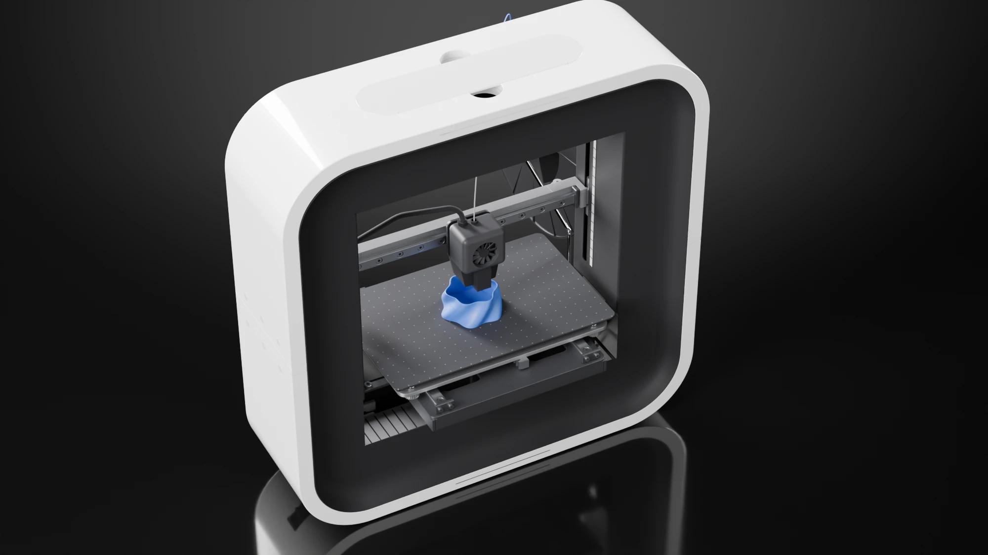
BEETHEFIRST. My design.
A window on the print.
A 250 × 250 mm window in a white ring, checked for how much of the plate an eye in front of the printer can see.
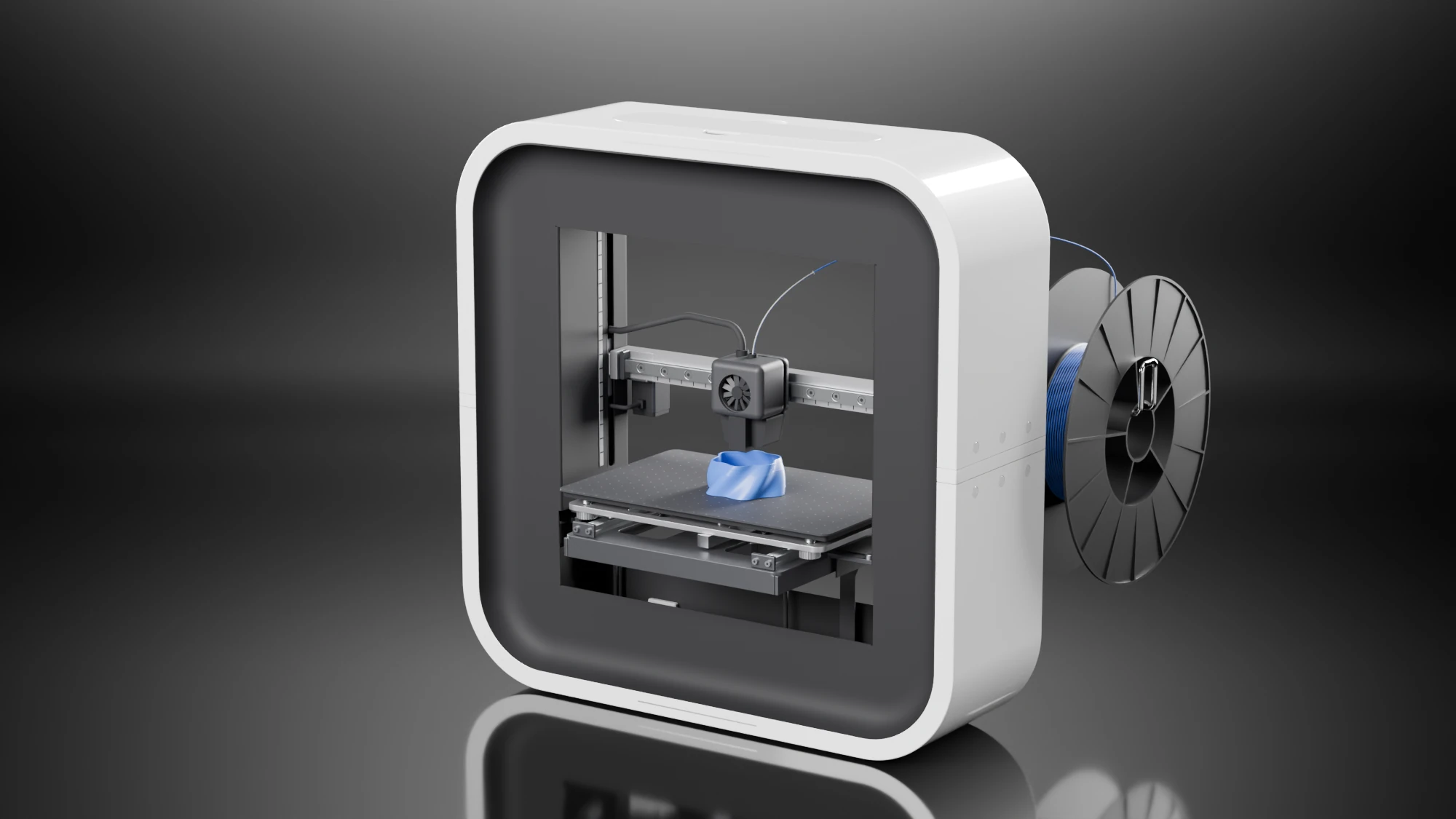
Render, 2026. The 2019 model.
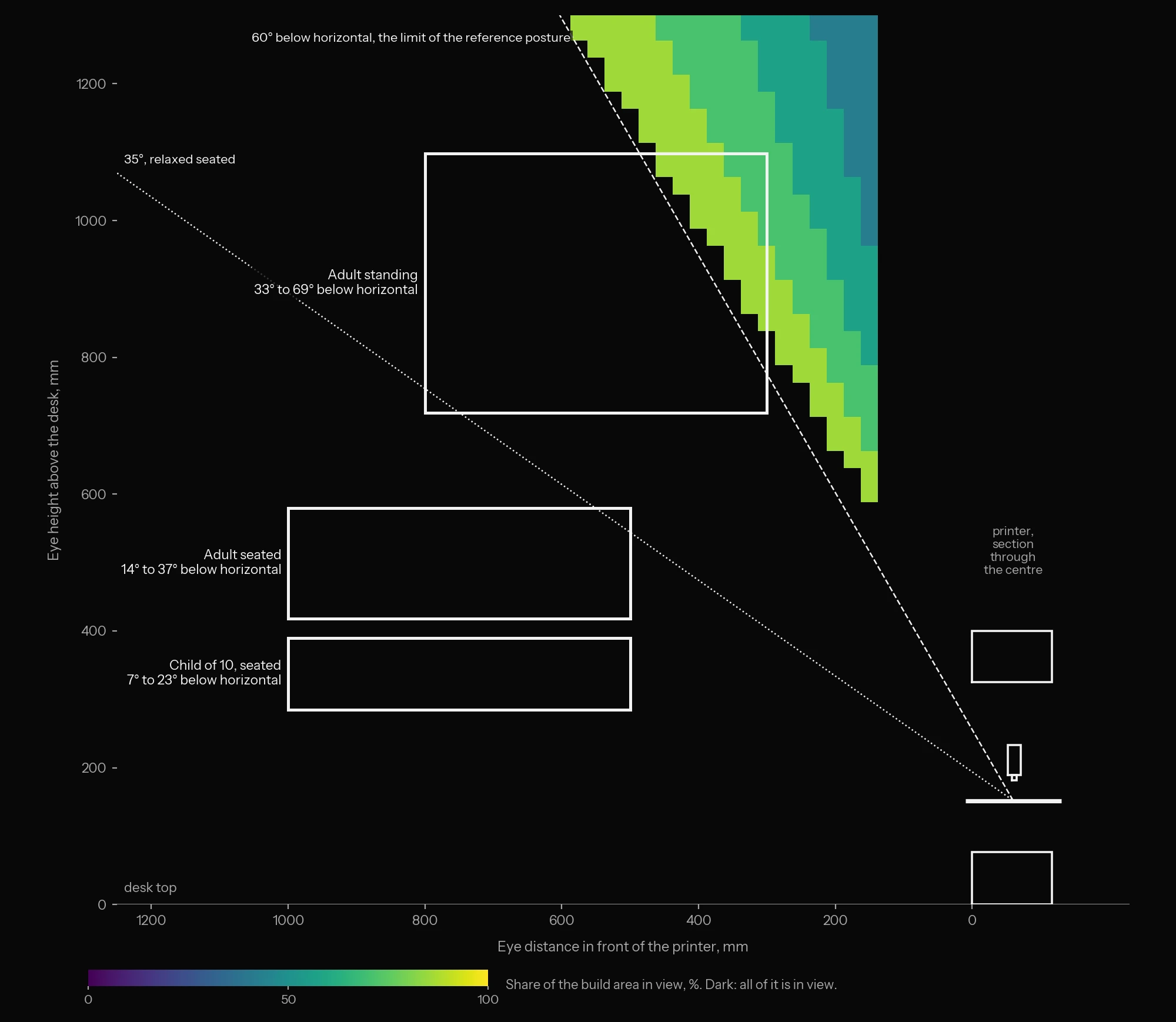
Checked against ISO 9241-5
Redrawn inside, in 2026.
The housing is the 2019 model’s own. Everything that prints was redrawn: 52 new objects in place of 26.
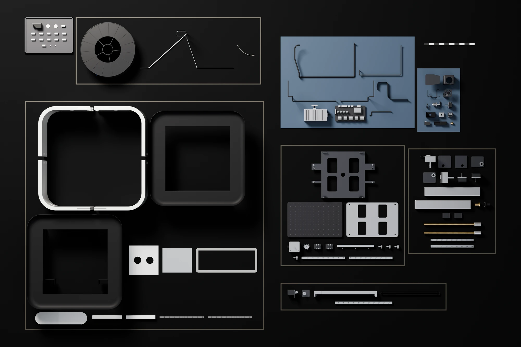
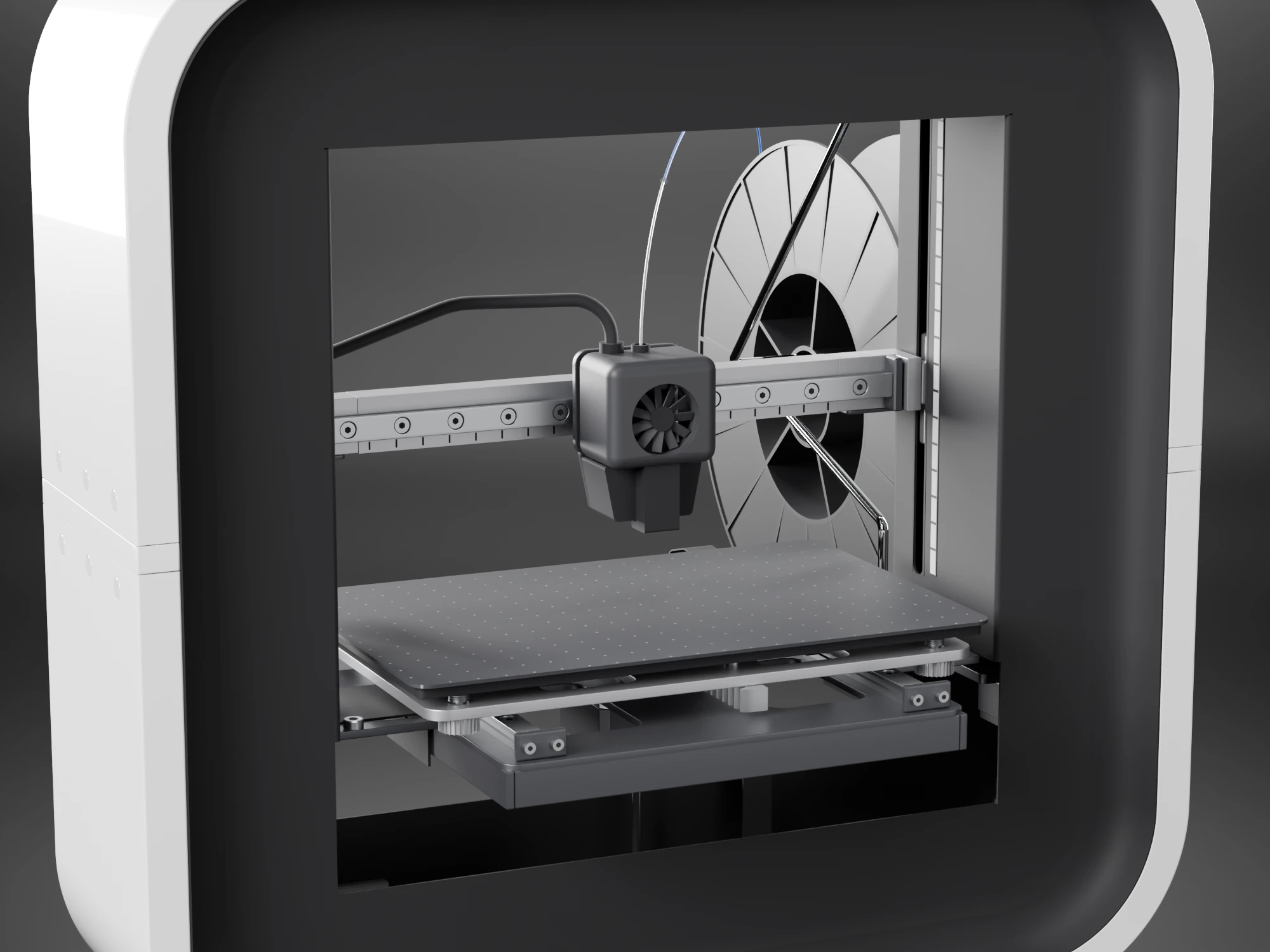
The print system. Through the window.
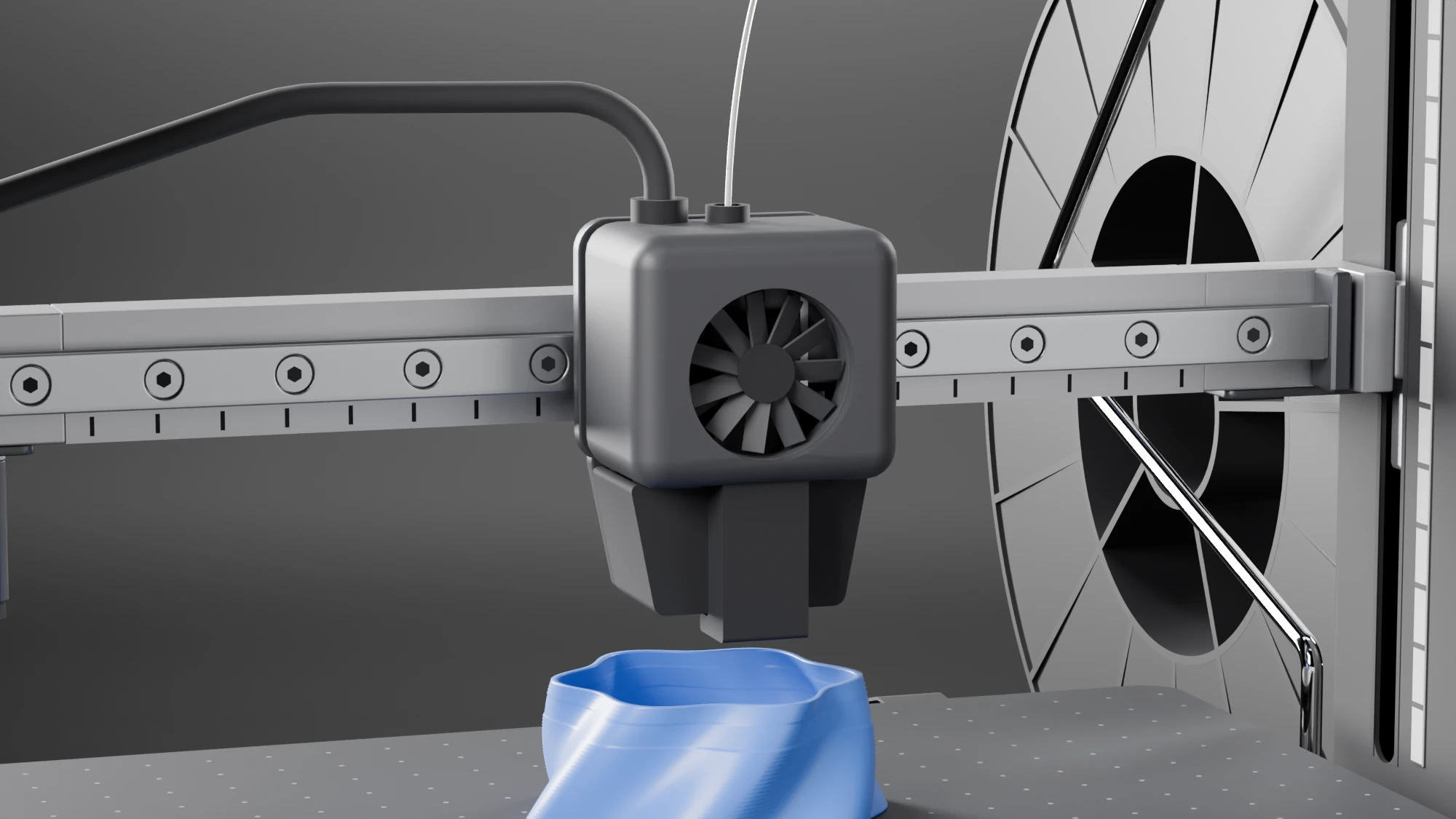
The toolhead
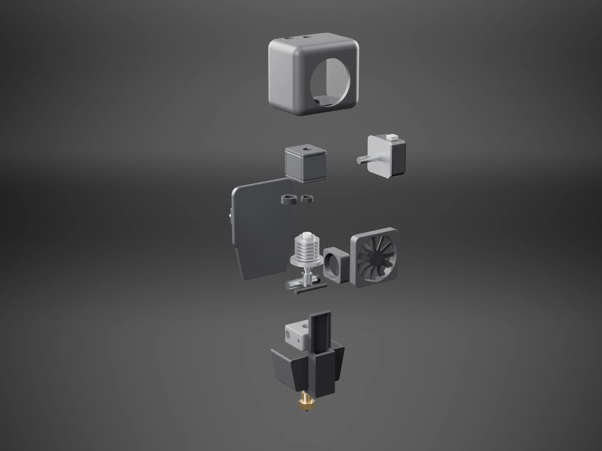
The head, apart
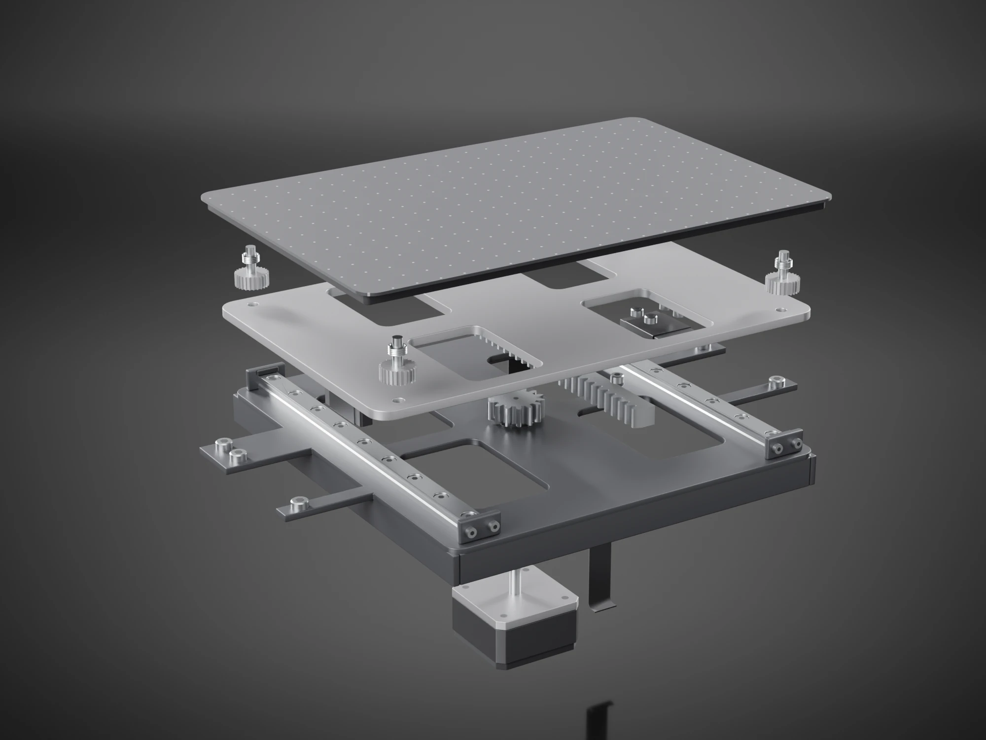
The bed, apart
59 W
peak power in direct current, as drawn
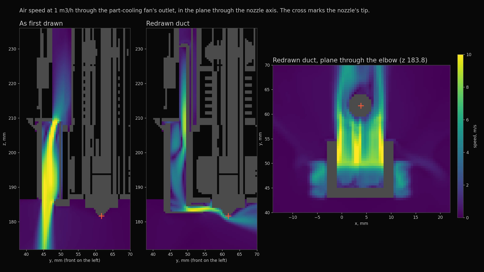
Airflow, in OpenFOAM. Air speed.
Packs for carrying.
A new travel position: the nozzle comes down to 10 mm above the plate and the bed slides back 9.8 mm.
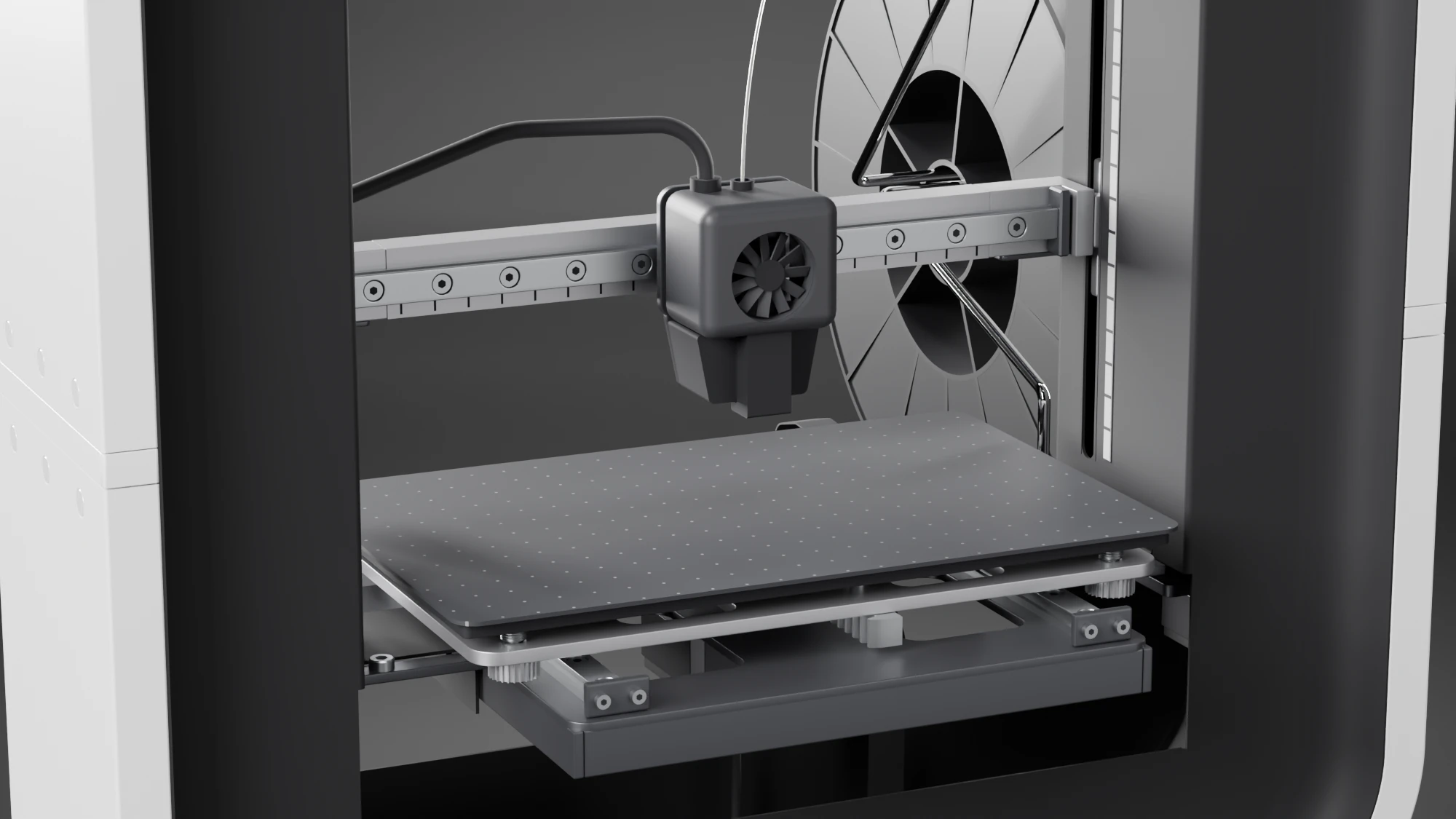
Print position
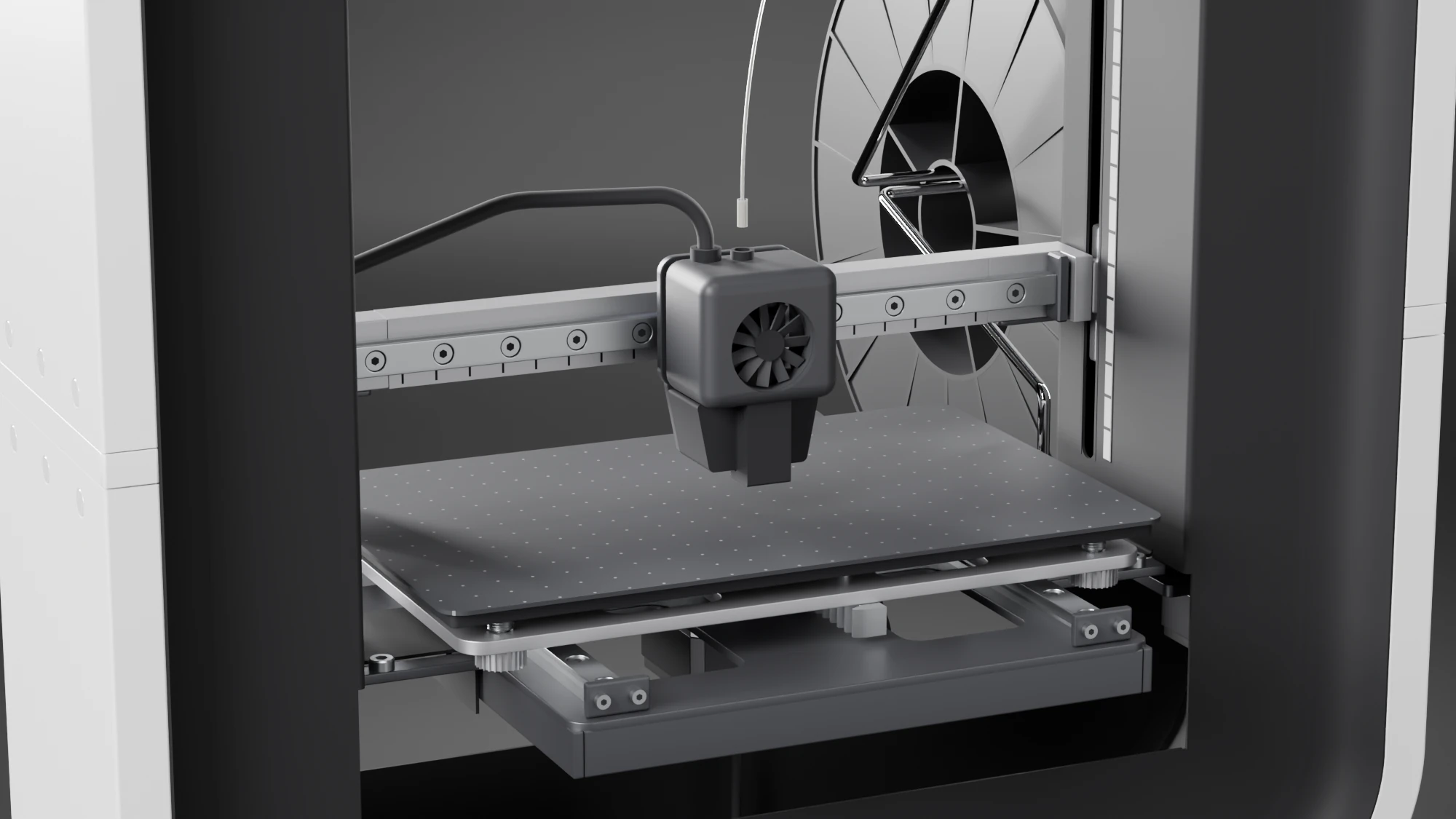
Travel position
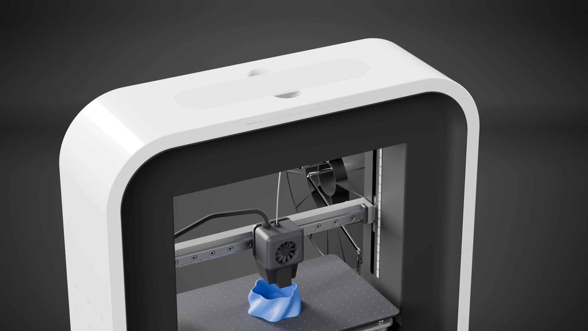
A grip in the roof. 204 mm, set flush.
Specifications
Published
- Outside size
- 400 × 400 × 140 mm
- Build volume
- 190 × 135 × 125 mm
- Mass
- 9.5 kg
- Nozzle
- up to 250 °C
The model
- Housing
- 398 × 117 × 400 mm
- Window
- 250 × 250 mm
- Plate
- 218 × 140 mm
- Peak power
- 59 W DC
How it was made
The 2026 studies at reading width: the casing joint, every axis, loads, heat and airflow, travel, the desk and the housing walls.
Read the full study
This design might look dated since it was produced in 2011. At the time, most 3D printers had a DIY, plywood construction look, but I bet on a more visually appealing design and it was widely embraced in the industry. While I was not a founder of the company, I worked closely with the founders at my alma mater's startup incubator to develop the design and product strategy.
As the sole designer, I sketched and 3D-modelled the concept, and it was part of my master's thesis. BEETHEFIRST was designed for education, DIY projects, and other introductory 3D printing purposes, and came with a learning curriculum and support and consulting services. It was easy to use and plug-and-play.
The model in 2026
The renders here are made from the 2019 KeyShot export of the model, lit again in 2026 in a dark studio. Two things in it were redrawn: a band that closes the seam between the upper and lower casing, and everything that prints. The housing, its liners, the reel on its rear arm and the grip in the roof are the 2019 model's own. The plate's size and height and the nozzle tip's position were kept from the 2019 model, so the measurements further down still hold.
The 2026 redesign and studies were done with two AI agents, Claude and Codex, which wrote the Blender and analysis scripts. I set the design and the questions, checked every render and number, and rejected what did not hold.
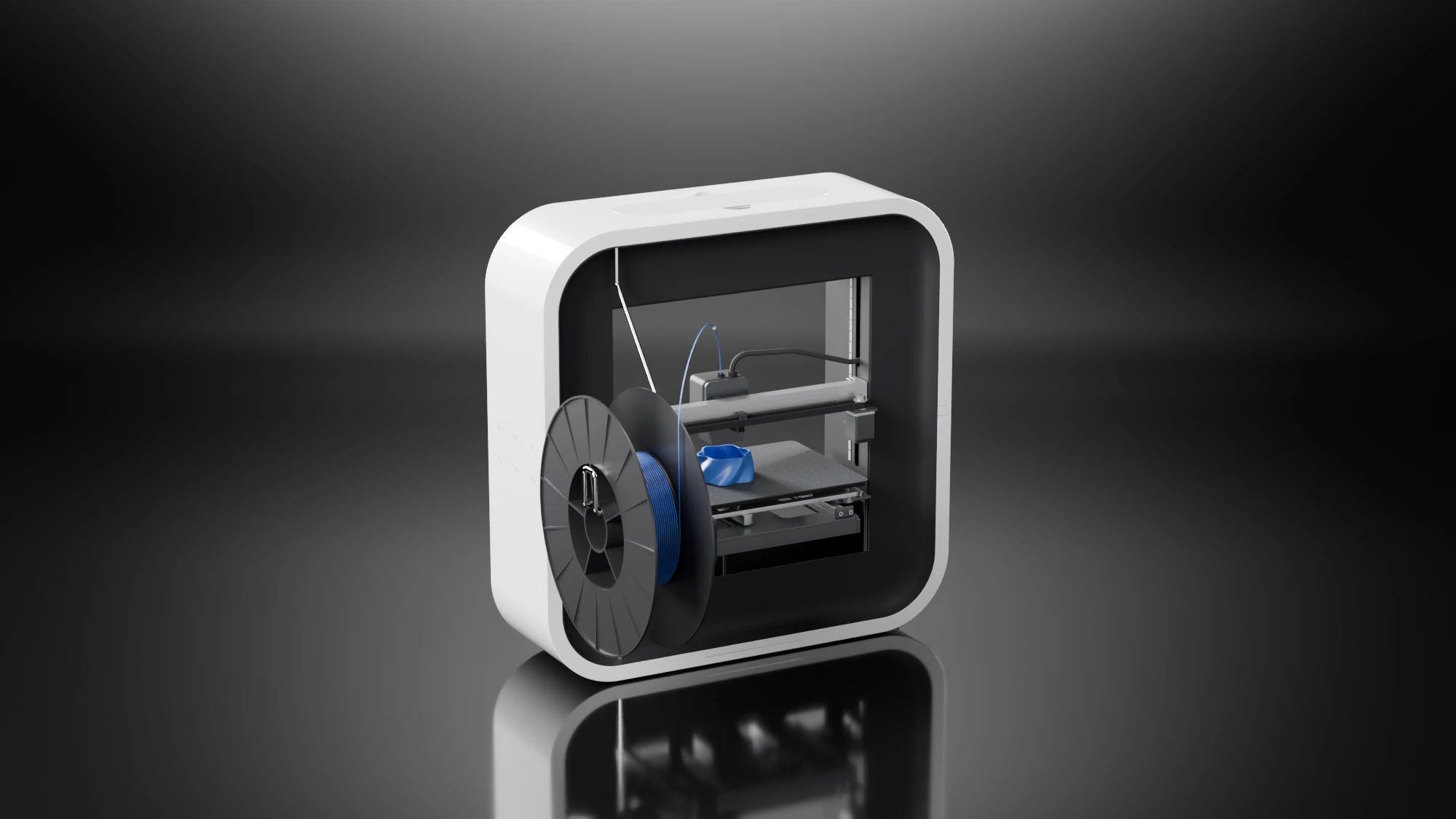
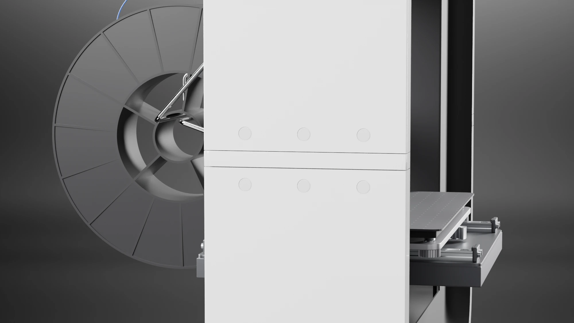
The casing joint
In the 2019 model the upper and lower halves of the white housing stop 9.7 mm apart and nothing joins them. The band is cut from the lower shell's own outline at that height. It is 9 mm tall and leaves a gap of 0.35 mm on each side, so the two halves still read as two parts.
The print system
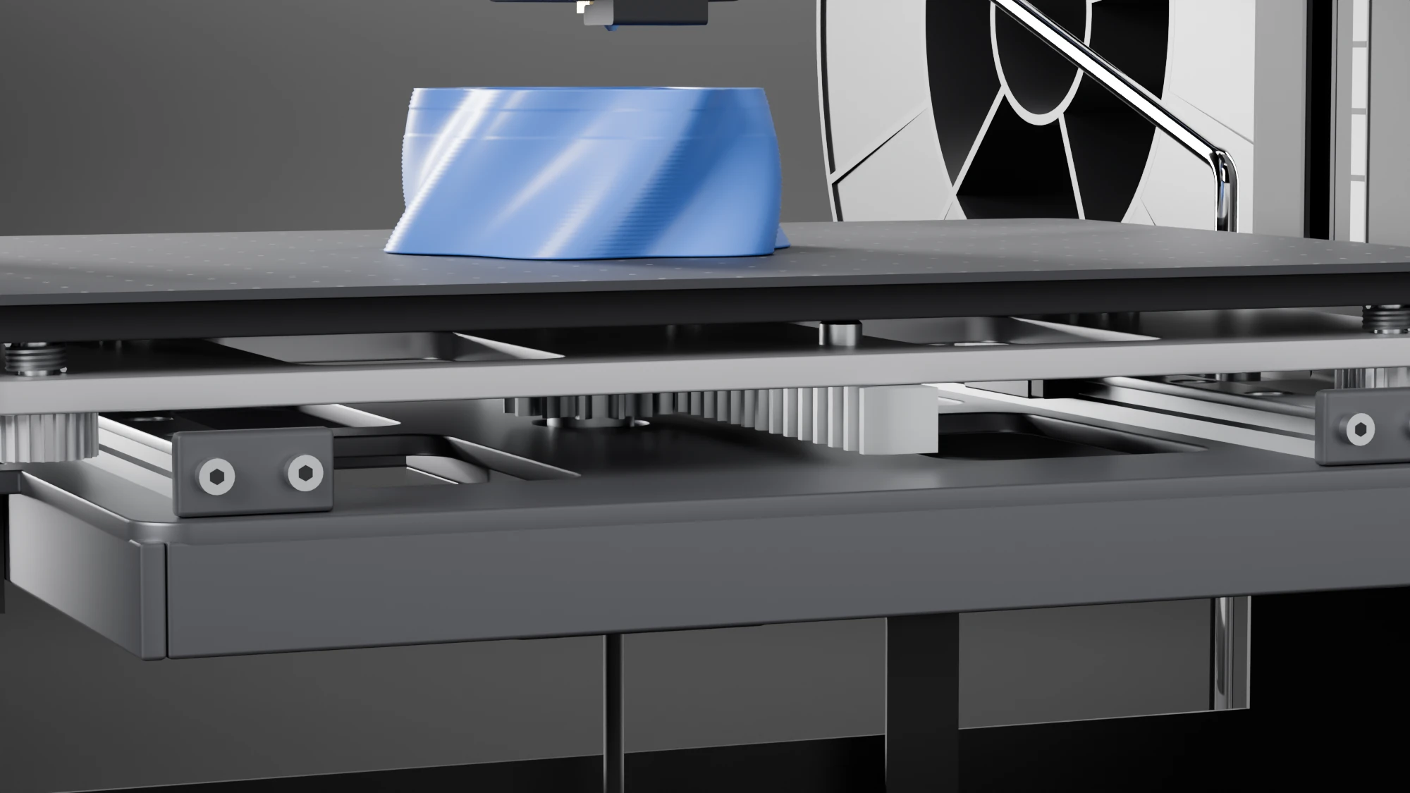
The tray, rods, motor, gear blocks, bed heater and extruder of the 2019 model are gone, 26 of its 57 objects, and fifty-two new objects take their place, most of them made of several parts and sixteen of them cables. The bed alone is a tray, two rails, a motor and pinion, a carrier, its blocks, a rack and the levelling screws. The X axis is a beam, a rail, a belt and a motor, and the head is a shell with a hot end, an extruder, two fans and a small board inside it. Each Z drive is a column, a rail, a lead screw and a motor, and a controller board and a power supply stand on the floor of the housing. The look follows current enclosed printers: graphite plastics and satin aluminium, a printed scale on the beam and beside each wall slot, no colour accent and nothing that glows. The head is a shell with one round fan opening in its front, after the toolhead of a Bambu Lab X1.
The vertical axes are not in the window. A tower stands in each side wall behind the liner, with its rail, screw and motor, and the electronics are on the floor below the bed. The 2019 model already has a vertical slot, about 7.5 mm wide, in each of those walls, and the X beam reaches the towers through it. Their parts are drawn further down.
The X axis
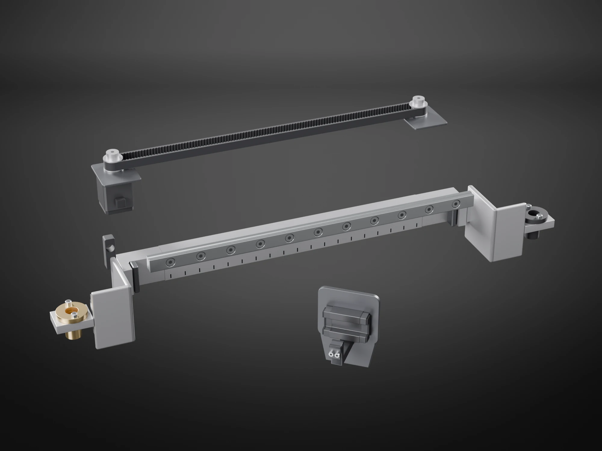
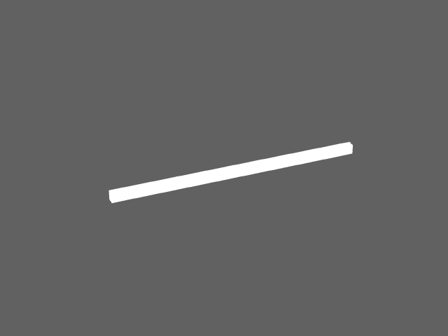
The 2019 model has two rods across the window, 6 mm across, and a slider that carries the head, so I drew an axis that does the same work with its parts: a rail, a block, a belt and a motor.
The beam is an aluminium extrusion that now sits 10 mm further back. That leaves room between it and the head for a 9 mm profile rail on its front face and the block that rides on it, without pushing the head's shell toward the nozzle, which the 2019 model fixes 62 mm behind the front face. The head hangs on the block through a plate. A 6 mm toothed belt runs behind the beam round two 16-tooth pulleys, driven by a 20 mm stepper under the left end. A clamp on the carriage goes under the beam and up behind it to hold the belt, so the head moves when the belt does. Each end block carries the beam through the slot in its side wall to the carriage on the tower.
The X axis
Point at a part, or step through the parts with the arrows.
- Beam and end blocks. An aluminium extrusion 12 mm deep and 20 mm tall, with a printed scale every 10 mm on its front lip. An end block at each end carries it through the slot in the side wall to the carriage on its tower, and a stop block closes each end of the rail. 248 × 22 × 20 mm
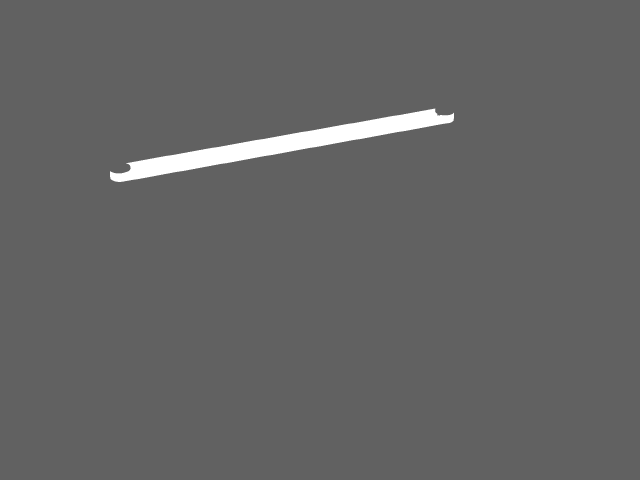
- Rail. A 9 mm profile rail on the front of the beam, with its screw heads sunk in counterbores every 20 mm. 227 × 9 × 6.5 mm
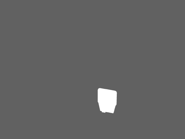
- Carriage. A block on the rail, the aluminium plate that is the back of the head, and an arm that goes under the beam and up behind it to a clamp round the belt. 42 × 35 × 54 mm
- Belt. A 6 mm toothed belt behind the beam, in one loop round two pulleys. The clamp holds one run of it, so the head moves when the belt does. 223 mm between pulleys
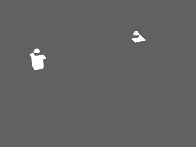
- Motor and pulleys. A 20 mm stepper under the left end block with its shaft up to a 16-tooth pulley, and an idler on a bracket under the right end block. 249 × 32 × 41 mm
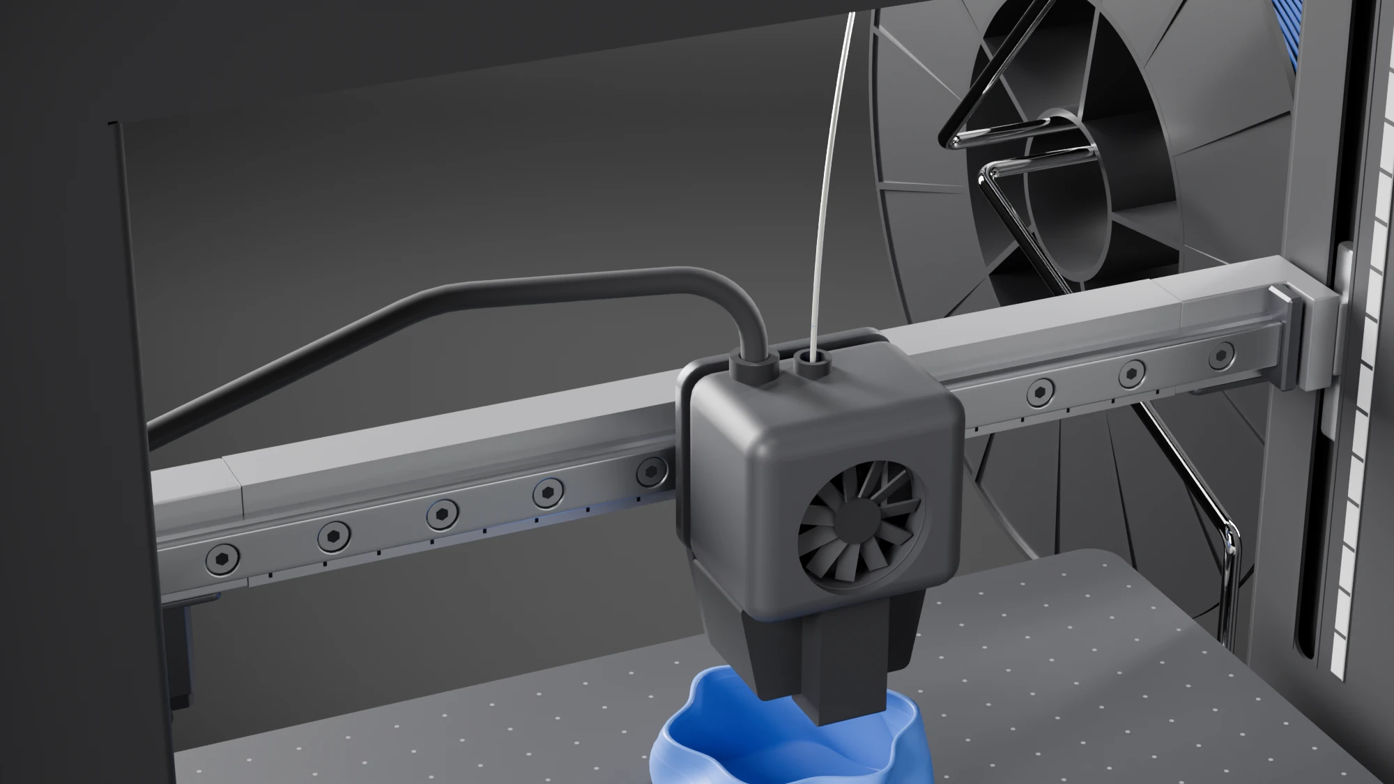
The housing sets one limit. Between about 84 and 98 mm behind the front face its ceiling is at 326 mm, so anything there has to stay below the top of the beam once the gantry has risen its full 96 mm. The belt and the motor are below it for that reason, and a belt on top of the beam would cost 12 mm of height. The head has 192 mm of free travel along the beam, from 100 mm to the left of its centre position to 92 mm to the right, against the 190 mm of the manual. The head, its clamp, the belt, the pulleys and the motor were swept along that travel and do not touch. The motor is a 20 mm stepper because that is what fits under the end block. The torque and the belt tension it needs are worked out further down.
The print head
I drew the head as the parts a head is made of, on the nozzle axis the 2019 model fixes and in front of the carriage plate.
The shell is hollow. It has the fan opening in its front, a hole at the top for the filament and one at the bottom for the heat break. Inside, a stack stands on the nozzle axis: the nozzle, a heater block with a cartridge heater and a thermistor, a heat break, a heatsink with six fins and its own small fan, and a PTFE tube up to a gear that pushes the filament. The gear stands just below the end of the 2019 model's filament tube, which stops at 233 mm. A small stepper on the right of the housing drives it. The round fan at the front blows into a hood behind it. A duct leads from the hood down in front of the heater block to an elbow under the cup, which ends 2.4 mm in front of the nozzle's hex and aims at the tip. The cup is 1 mm clear of the heater block in front and underneath.
A small board sits on the shell's left wall. The head's cable ends in a connector on it, and its other connectors take the leads for the motor, the heater, the thermistor and the two fans. The leads to the heater cartridge and the thermistor come up a channel between the shell wall and the heatsink fan, through a slot in the shell's floor, from the heater block. The motor's lead crosses over the top of the extruder. The leads are 1 to 1.8 mm across.
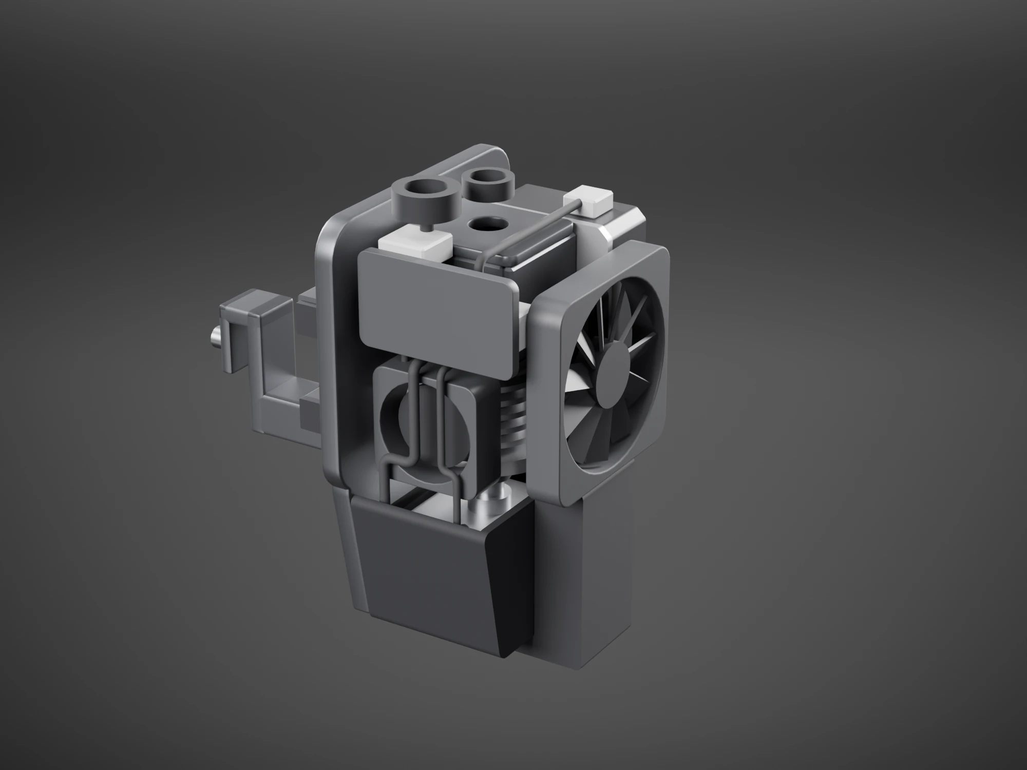
The extruder motor is a 20 mm stepper because that size fits beside the gear in a shell 42 mm wide. Its length, the sizes of the two fans and the number of fins were chosen to fit and are not taken from a catalogue. The heat and the airflow are worked out further down.
The Z axes
A beam lifted by two different drives would not be driven evenly, so I drew the same drive in both walls.
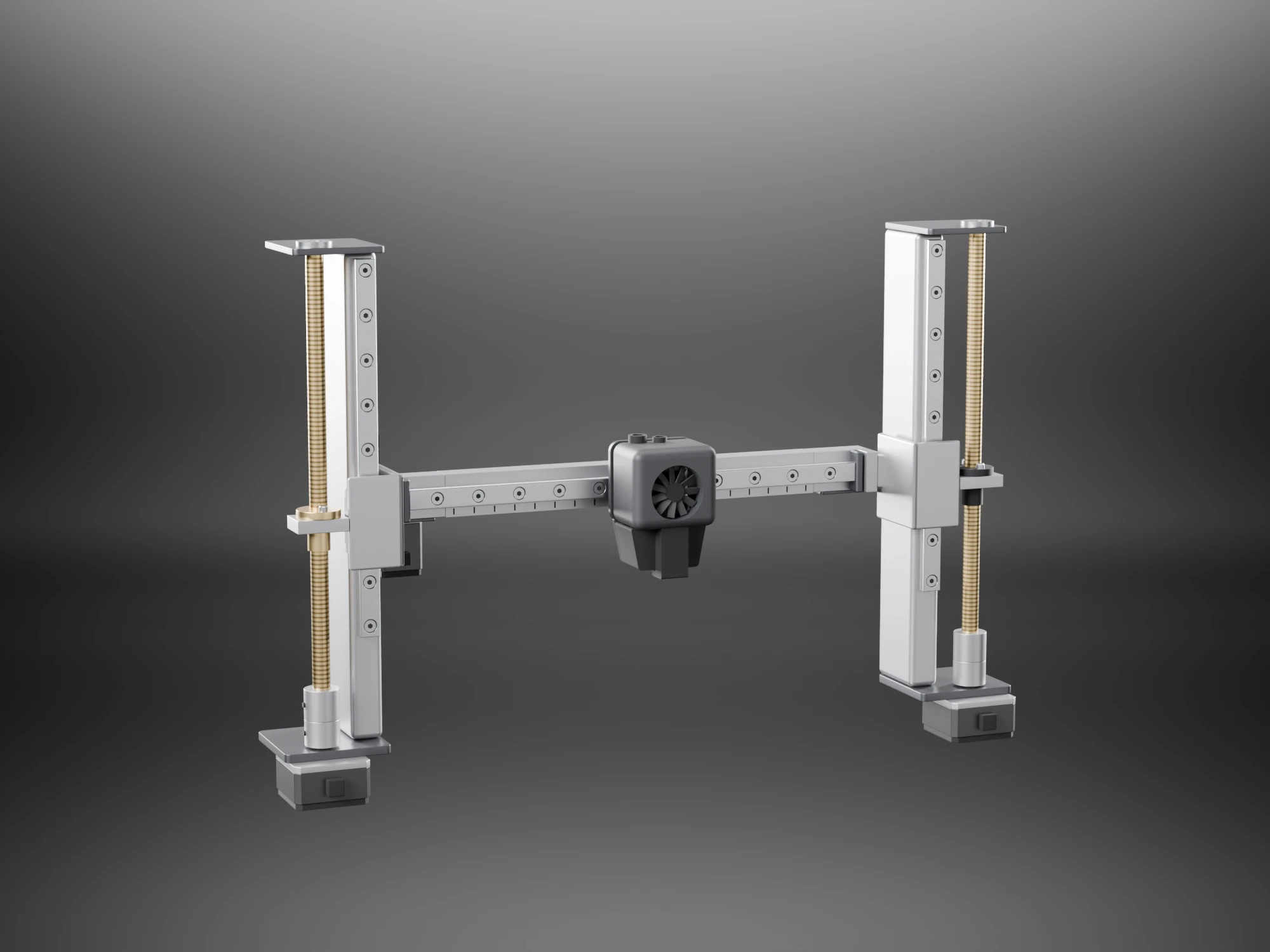
An aluminium column stands behind each liner. A 9 mm profile rail is screwed to its front face, and a block on it is bolted to the plate of an L bracket. The bracket's cheek runs back to the tongue that passes through the wall slot to the beam, and its arm reaches out to a brass flange nut on a T8 lead screw beside the column. The screw turns in a flanged bearing in a plate on top of the column, and a coupler at its foot joins it to the shaft of a 35 mm stepper hung under the base plate. Turning both screws lifts the beam, the head and the nozzle.
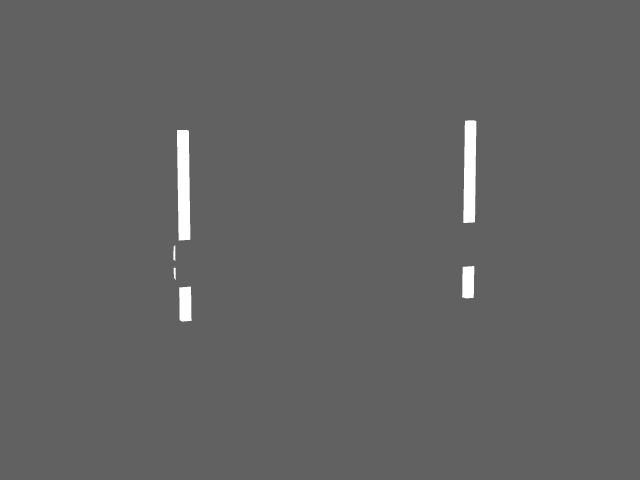
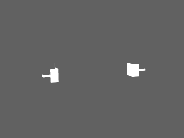
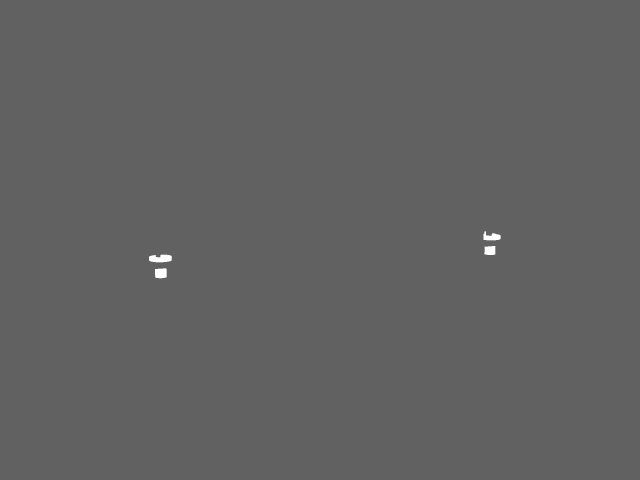
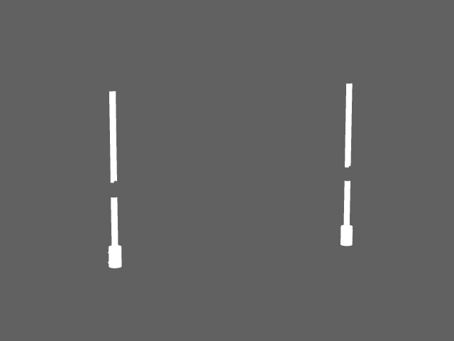
The Z axes
Point at a part, or step through the parts with the arrows.
- Towers. An aluminium column in each side wall behind the liner, with the rail screwed to its front face and a plate under its foot. The drive is the same on both walls. 15 × 36 × 222 mm
- Rails and blocks. A 9 mm profile rail with its screw heads sunk every 20 mm, and a block on it with end caps and seals. The block is bolted to the carriage's plate. rail 170 mm, block 20 × 31 × 10 mm
- Carriages. An L bracket on each tower. The block is bolted to its plate, the cheek runs back to the tongue that passes through the wall slot, and an arm reaches out to the nut. The left cheek also carries the clamp for the head's cable. 52 × 39 × 42 mm
- Nuts. A brass flange nut in the arm of each carriage, held by two screws. Turning the screw moves the nut, and the carriage with it. 20 mm flange
- Lead screws. A T8 screw between a flanged bearing in the top plate and a coupler on the motor's shaft. The thread is a surface pattern, not geometry. 8 mm, 212 mm long
- Motors. A 35 mm stepper hung under each base plate, with its 5 mm shaft up into the coupler and its connector on the front side. 35 × 35 × 20 mm
- Plates and bearings. A base plate under the column and the motor, and a top plate on the column with the flanged bearing that holds the screw's upper end. 49 × 49 × 4 mm
The beam, the head and the nozzle have 126 mm of free height on the towers. They go 30 mm below the print position, where the nozzle reaches the plate, and 96 mm above it, where the housing's ceiling stops them, against the 125 mm of the manual. The towers stand 5.6 mm from the housing, and the clamp on the left bracket is 1.0 mm from the left tower. The model does not give the thread's lead, so the screws' torque is worked out further down for two common leads.
The bed mechanism
I drew the bed mechanism as the parts it is made of, to show how they move as well as where they go.
The 2019 model has a motor and a gear train under the bed, and I kept that idea. A stepper under the tray turns a 14-tooth pinion, and the pinion meshes a rack on the underside of the carrier. A belt would need its pulleys at the ends of the stroke, outside a housing that is 117 mm deep, and the stroke is 140 mm. The motor and the pinion stay inside the housing, 60 mm behind the front face, and only the rack moves.
The carrier is an aluminium plate on two blocks, one on each of two 172 mm rails. The rails are screwed to a tray of formed sheet aluminium, and a stop block with a pad closes each end. Four screws, each with a spring under the heater slab and a knurled wheel under the carrier, set the plate level.
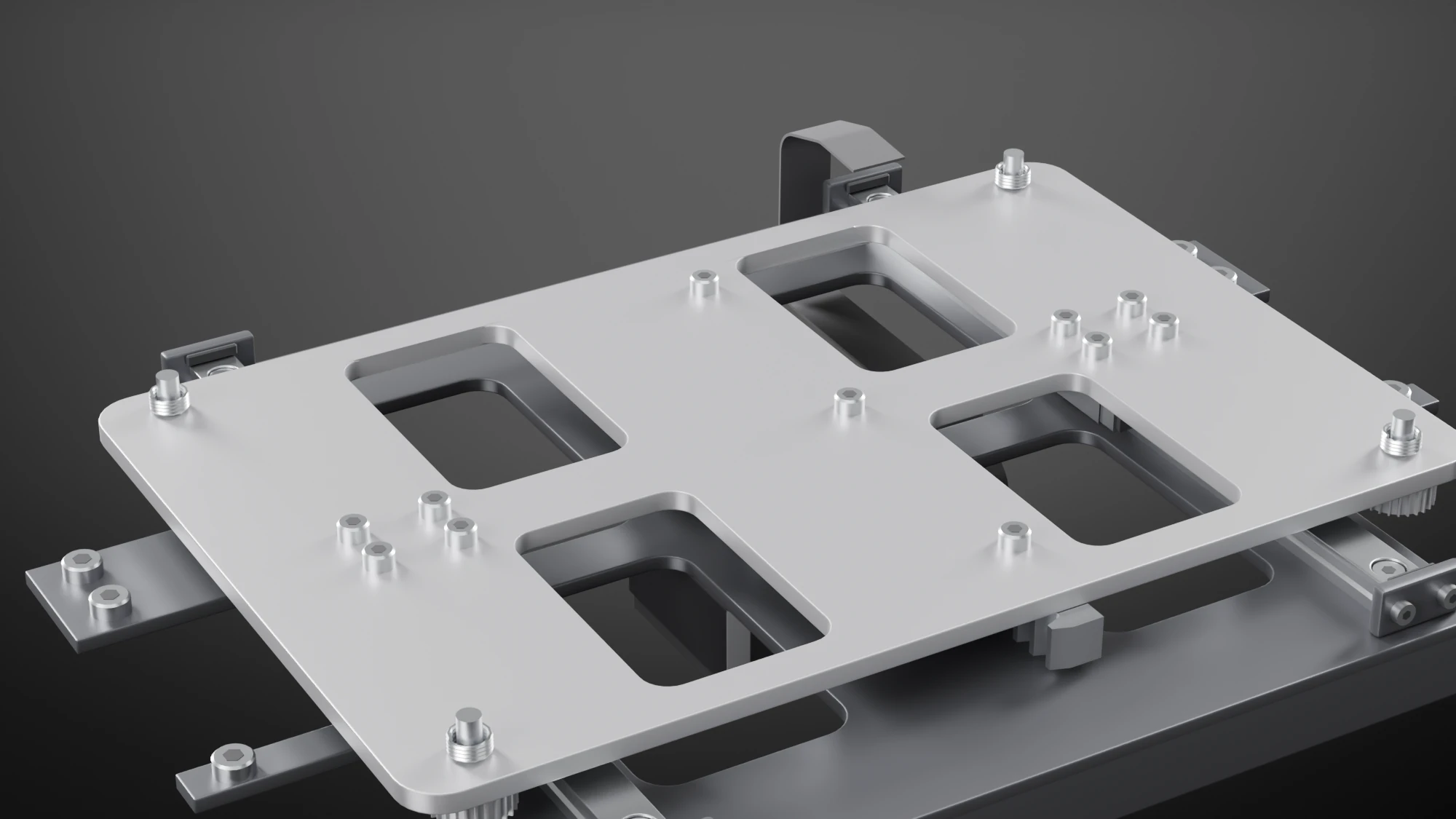
A block is 31 mm long and the stops take a few millimetres more, so 172 mm of rail gives a stroke of 140 mm, and the tray stands out 32 mm from the front of the housing and 35 mm from the back. In Blender the pinion was turned with the bed through 47 positions along its stroke, and the teeth did not touch the rack at any of them. The rail, block and gear sizes follow common catalogue sizes and were chosen to fit the space. The loads and the torques are worked out further down. The heater's cable is a flat ribbon from the slab's back edge to the board, and no heating element is drawn in the slab.
Electronics and wiring
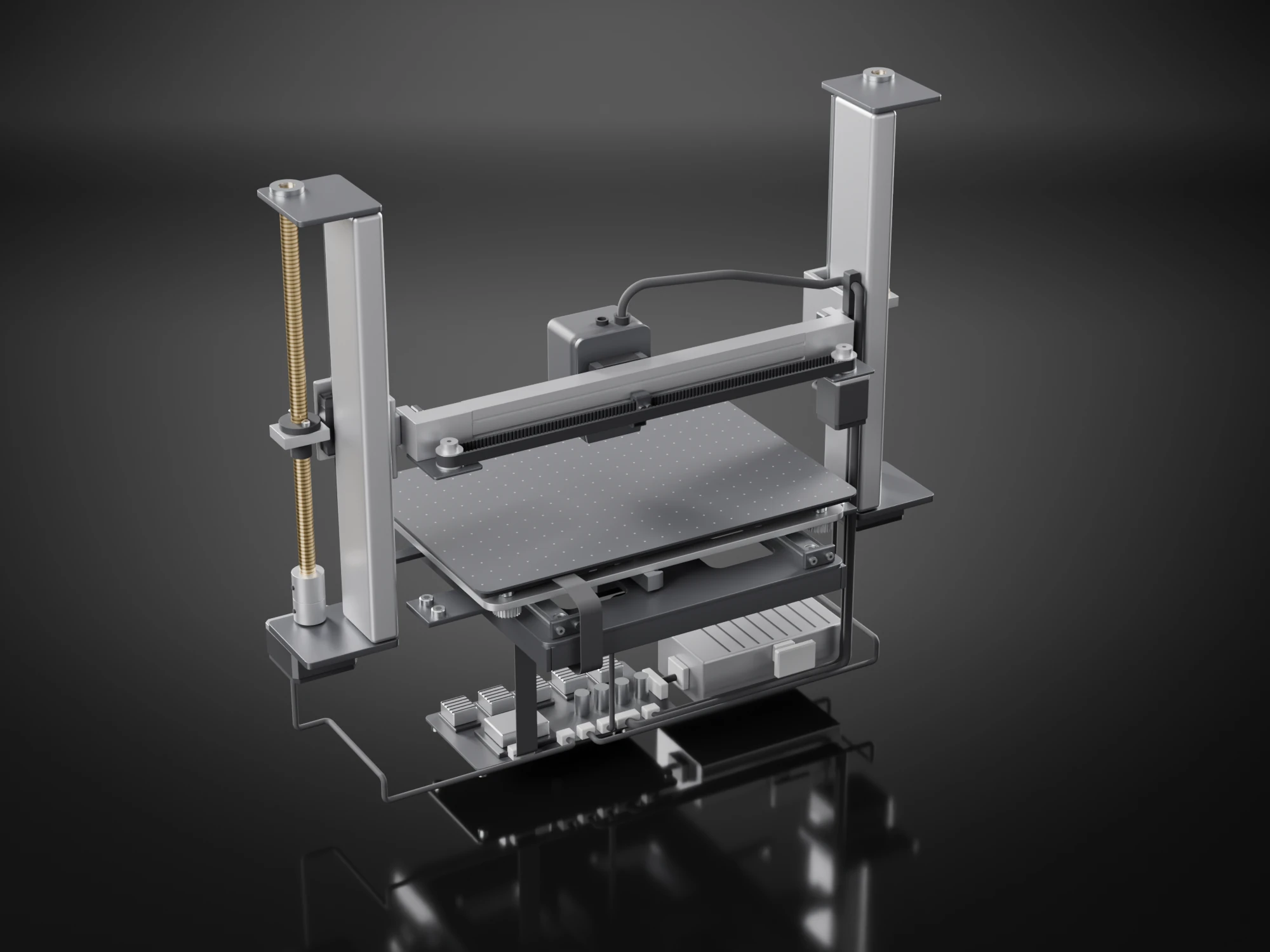
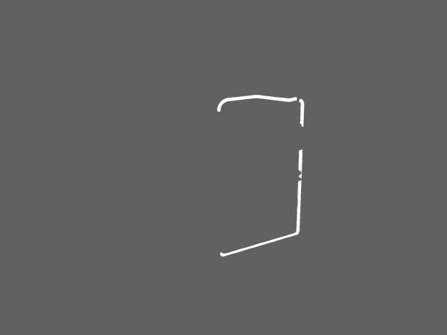
The 2019 model has no electronics. A printer needs a controller, a power supply and cables to every motor, the heater and the head, so I drew them to see where they go.
The controller is a 120 × 62 mm board on five standoffs on the floor of the housing, with five stepper driver modules, a processor module, four capacitors and a row of connectors along its rear edge. The power supply is a ribbed case, 90 × 48 × 29 mm, to its left, with a short lead to the board's power block and a mains lead to an inlet against the back skin of the housing. The housing has no hole for that inlet.
Every cable arrives at the back of the board. The head's cable goes over the beam, through the left wall slot and a clamp on the left carriage, and down the 8 mm gap between the wall and the left tower to the floor. The X motor's cable takes the same way below it. The Z motors' cables go down the front of their wall cavities and back along the floor, the Y motor's drops straight down, and the bed's is a flat ribbon that leaves the heater slab's back edge, passes behind the tray and comes forward under it. On the floor each runs in its own lane at the height of its connector, so none crosses another.
Electronics and wiring
Point at a part, or step through the parts with the arrows.
- Head cable. One black cable from the gland on top of the head, over the beam, through the left wall slot and a clamp on the left carriage, down the gap behind the left tower and along the floor into the widest connector on the board. 4.8 mm across
- X motor cable. From the connector on the X motor's front, out through the same slot below the clamp, and down the same gap to the board. 3 mm across
- Z motor cables. One from each Z motor: out of the connector on the motor's front, down the front of the wall cavity, and back along the floor behind the board. 3 mm across
- Y motor cable. From the connector at the back of the bed's motor, down behind the board to its connector. 3 mm across
- Bed cable. A flat cable from the back edge of the heater slab, down behind the tray, forward under it and down to the board. No heating element is drawn in the slab. 12 × 0.6 mm
- Controller board. A board on five standoffs with five stepper driver modules and their heatsinks, a processor module, four capacitors, and a row of connectors along its rear edge, where every cable arrives. 120 × 62 × 1.6 mm
- Power supply. A ribbed case with a lead from its terminals to the board's power block and a mains lead to an inlet against the back skin of the housing. The housing has no hole for the inlet. 90 × 48 × 29 mm
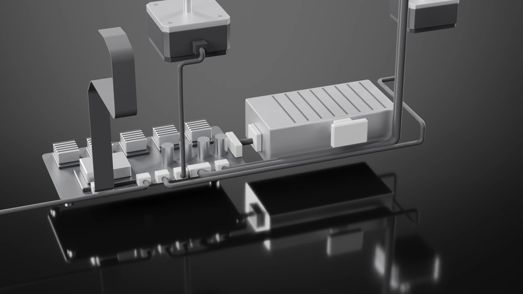
No cable passes through the housing or another part. A cable shares volume with something only where it ends in a connector, a gland or a sleeve, or joins another cable end to end. Each was drawn along a path that bends no tighter than its own radius. The cables are drawn at the print position and are not swept: the head's cable and the X motor's cable meet the fixed run in the corridor at a joint, and nothing takes up the 126 mm that the beam travels. The bed's ribbon is not swept along the bed's stroke either. The wire sizes, the connectors, the board's layout and the power supply's size were chosen to look right and were not taken from a design. The current, the voltage drop and the heating of each cable are worked out further down.
Loads, heat and airflow
I worked out the numbers on the model: masses, loads, current, heat and airflow. Masses come from the model's volumes and handbook densities. A number from a published source is named, and every other number is an assumption of mine, tested over the range given. The motors are reference motors of the model's frame sizes from catalogue pages, not the motors the printer had. These are hand calculations and one airflow simulation. None of it was tested on a built printer.
Loads and torques
The head weighs 0.12 kg, the beam and everything on it 0.59 kg and the bed 0.77 kg, so the print system as drawn is 3.7 kg of the manual's 9.5 kg. The loads are small. At an assumed 3000 mm/s² the X belt carries 0.4 N, against about 26 N of working tension for a 6 mm GT2 belt, and the bed's pinion needs 2.5 N cm. Each Z screw lifts 3.4 N. The largest moment on any rail block is 0.08 N m, against 7.35 N m for a catalogue MGN9C block, and the beam bends less than 0.001 mm under the head.
| Check | Needed | Reference | Margin |
|---|---|---|---|
| X motor at 3000 mm/s² | 0.20 N cm | 1.4 N cm, a 20 mm stepper | 6.9 times |
| Y motor at 3000 mm/s² | 2.5 N cm | 13 N cm, a 42 mm pancake stepper | 5.2 times |
| Z motor, T8 screw with a 2 mm lead | 0.29 N cm | 12.5 N cm, a 35 mm stepper | 43 times |
| Z motor, T8 screw with an 8 mm lead | 0.64 N cm | 12.5 N cm | 19 times |
| X belt at 3000 mm/s² | 0.40 N | 26 N working tension | 65 times |
| Z block, pitch moment | 0.08 N m | 7.35 N m | 95 times |
A T8 screw with a 2 mm lead holds the beam up when the motors are off, because its 5.2° lead angle is under the 6° to 11° friction angle of brass on steel. With an 8 mm lead it would not, and the motors would have to hold 0.2 to 0.3 N cm against the beam's weight. The model does not say which lead the screws have.
Current and supply
With every motor at its reference rated current, the hot end heating, the fans and the controller, the peak is 59 W of direct current. The bed heater the 2019 model draws, sized to reach 60 °C in five minutes, would add 55 W. At 85 to 90 % efficiency that is 0.3 A at 230 V without the bed heater and 0.6 A with it, against the manual's rating of 2.0 A at 200 to 240 V (3.0 A at 100 to 120 V). The rating is a maximum for the label and does not say what the printer drew.
On an assumed 24 V bus, no cable drops more than 0.15 % of the voltage or warms more than 3.3 K in still air. The head cable carries about 1.25 A in its heater pair, which is 2.1 A per mm² in 0.6 mm² conductors, and if a third of its section is copper the twelve conductors fit in its 4.8 mm. The bed's flat cable would carry 2.3 A at 24 V, or 4.6 A at 12 V.
Heat
Holding a nozzle at 220 °C takes 7 to 21 W, depending on how much air moves over the block, plus about 2 W to melt plastic at 5 mm³/s. A 25 W heater takes the block from 25 °C to 218 °C in 95 s, and a 40 W heater in 55 s.
The model draws a heat break with no bore. With a 2 mm bore it passes 3 to 5 W from the block to the heatsink, and the 16 mm fan has to take that away. At an assumed 20 to 65 W/m² K over the fins, the heatsink's base sits between 114 and 65 °C when the nozzle is at 220 °C. PLA softens at 60 to 65 °C, so on this estimate the filament inside the heatsink is at or over its glass transition, and the heat break and the heatsink are the weakest part of the hot end as drawn. I left them as drawn.
In the first drawing the heater block touched the dark cup round it, and a plastic cup at 220 °C fails: ABS softens at about 105 °C. I moved the cup 1 mm clear of the block in front and underneath. By a lumped estimate it still sits at 100 to 150 °C, so the cup needs a high-temperature plastic, which the model does not choose.
The supply, 90 × 48 × 29 mm, loses 7 to 11 W at the peak without the bed heater, and its case would stand 24 to 58 K above the room. With the bed heater it would be 45 to 112 K over, which is too small a case for that load. If the housing were closed, its air would rise 15 to 22 K at the same peak. Its window is open, so the rise is less.
The 2014 reviews describe an unheated bed, while the 2019 model draws a heating resistance under the plate. A plate at 60 °C loses 22 W from the slab and the plate.
Airflow
I ran the part-cooling air in OpenFOAM, steady, with a k-omega SST model, on a grid of 0.5 mm cells made from the head's solids. The fan is a uniform inlet on the disc behind its blades, so the case gives the pressure the fan has to supply for a given flow.
As first drawn, the duct's inlet was a 1.5 mm gap under the fan's frame and its outlet pointed straight down, 15 mm in front of the nozzle. At 1 m³/h the fan had to supply 62 Pa, and the air 3 to 8 mm in front of the nozzle moved at 0.2 m/s. I redrew the duct as a hood open to the fan's outlet, a run down in front of the cup and an elbow that ends 2.4 mm in front of the nozzle's hex, 1.4 mm tall, with its underside 0.7 mm above the tip's level. An elbow reaching below the tip would hit a print. The same flow now needs 39 Pa and moves at 2.4 m/s in front of the nozzle, with a jet of up to 10 m/s. Refining the cells to 0.25 mm moved the pressure by 12 % and the speed by 3 %. A 1 mm grid could not resolve the outlet and gave twice the pressure.
The fan's own curve is not in the model. On three catalogue 25 mm fans, with a straight-line curve assumed, the flow comes to 0.6 to 1.3 m³/h and the speed in front of the nozzle to 1.5 to 3.1 m/s. The jet takes about 1.2 to 1.8 W from the nozzle at 220 °C.
What the numbers changed
Three things in the head changed: the cup is 1 mm clear of the heater block, the duct opens to the fan's outlet, and its elbow aims at the tip. The heat break, the heatsink, the cup's material and the supply's size are left as drawn and not settled. I did not work out the motors' speed-torque curves, the fans' own curves and noise, a conjugate heat simulation of the hot end, vibration of the gantry or belt dynamics, and nothing was tested on hardware.
Travel
The 2019 model has no way to pack the machine for carrying, so this is a new drawing. In the travel position the head and beam come down until the nozzle is 10 mm above the plate, and the bed slides back 9.8 mm, which brings the front of the plate level with the front of the ring.
The plate stays one flat piece. It does not fold in half, because a hinge across a 218 × 140 mm plate would land inside the 190 × 135 mm build area. One flat piece also leaves the depth where it was. The plate is 139.9 mm deep, close to the 14 cm outside depth in the manual, and the housing is 117 mm, so sliding the bed back moves the overhang from the front to the rear. The tray under the plate does not move, and it stands 32 mm out of the front of the housing and 35 mm out of the back. Nothing locks in the model, and no latch is drawn.
Drawings
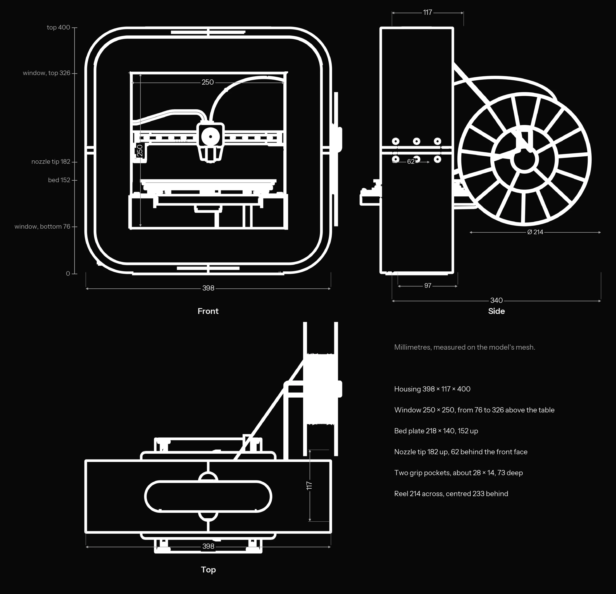
The housing is 398 mm wide, 400 mm tall and 117 mm deep. The window through it is 250 mm square, with its sill 76 mm above the table. The plate sits at 152 mm and the nozzle tip at 182 mm, 62 mm behind the front face. The manual lists the outside size as 40 × 40 × 14 cm and the mass as 9.5 kg. The model comes to 127 mm deep once the front edge of the plate is counted, and to 184 mm with the tray under it, so it is the design as it stood in the 2019 model and not a copy of the shipped printer.
Model and published figures
- Housing, model
- 398 × 117 × 400 mm
- Outside size, manual
- 400 × 400 × 140 mm
- Window, model
- 250 × 250 mm
- Plate, model
- 218 × 140 mm
- Build volume, manual
- 190 × 135 × 125 mm
- Mass, manual
- 9.5 kg
Inside the model
The 2019 model holds 57 named objects, and the names are Portuguese. Four solid shells make the white housing and two sheet liners line the window. In the 2019 model the shells are called contraplacado, plywood, and twelve small parts are called rebite_madeira, wooden rivets. Of the 57 objects, 31 remain in these renders: the housing, its liners and rivets, the base sheets, the top plate and grip, and the reel on its arm. The other 26 made up the tray, the rods, the motor, the two gear blocks, the bed heater and the extruder. They were replaced by the fifty-two print system objects described above, and the casing band added two more.
Seeing the print
Through the window the whole build area is in view from any eye position below a limit that rises with distance: 575 mm above the desk at 150 mm from the printer, 825 mm at 300 mm, 975 mm at 400 mm and 1,300 mm at 600 mm. The head of the window starts to hide the back of the plate about where the line of sight passes 60° below horizontal, which is the steepest line of sight in the 1998 edition of ISO 9241-5 for its reference posture. A seated adult at 500 to 1,000 mm looks 14° to 37° below horizontal and a child of ten at a school table 7° to 23°. The tallest standing adults, leaning in to 300 mm, look as steeply as 69° and lose the back of the plate. The study counts the housing only, not the head or the beam.
The hot end and the window
The nozzle tip is 62 mm behind the front face, in a 250 mm square window with nothing across it. The manual gives the nozzle as up to 250 °C and says it is shielded and must never be touched. Make gives about 220 °C. CENELEC Guide 29 puts the burn threshold for one second of contact with bare metal at about 64 to 70 °C, and gives two seconds as the contact period for children of 6 to under 14 and four seconds for children of 2 to under 6.
The window is wider than any hand in the data: hand breadth runs from 59 mm for a 10-year-old girl at the 5th percentile to 96 mm for an adult man at the 95th. The ISO 13857 table asks for 850 mm of distance to reach past an opening of 40 to 120 mm, and the window is larger than any row in it. Nothing in the model sits between the window and the nozzle. The manual relies on supervision instead: it calls the printer designed for adults and allows children only with an adult watching.
Reach to the hot end
- Nozzle tip behind the front face
- 62 mm
- Window
- 250 × 250 mm
- Nozzle, manual
- up to 250 °C
- Nozzle, Make
- about 220 °C
- Bare metal, one second, burn threshold
- about 64 to 70 °C
Carrying it
The top carries a bar 204 mm long, 49 mm deep and 43 mm tall, set flush in the roof, with a half-round pocket at the middle of each long side, 28 mm wide, 14 mm from front to back and 73 mm deep. The manual says the handle comes out when one side is pressed and lifted, and gives it no load rating.
Against published numbers the bar is long enough, since NIOSH asks for handles at least 115 mm long and the widest adult hands in the data, men at the 95th percentile, are 96 to 99 mm. Its 49 mm depth sits inside the 32 to 51 mm that NIOSH and Cal/OSHA give for a power grip on a tool. The mass is the open question. At 9.5 kg the printer is 24 percent of the body weight of a median 10-year-old girl and 38 percent of a 5th-percentile one. The carrying guidance in the sources below excludes one-handed carries, so it gives no limit for this case.
On the desk
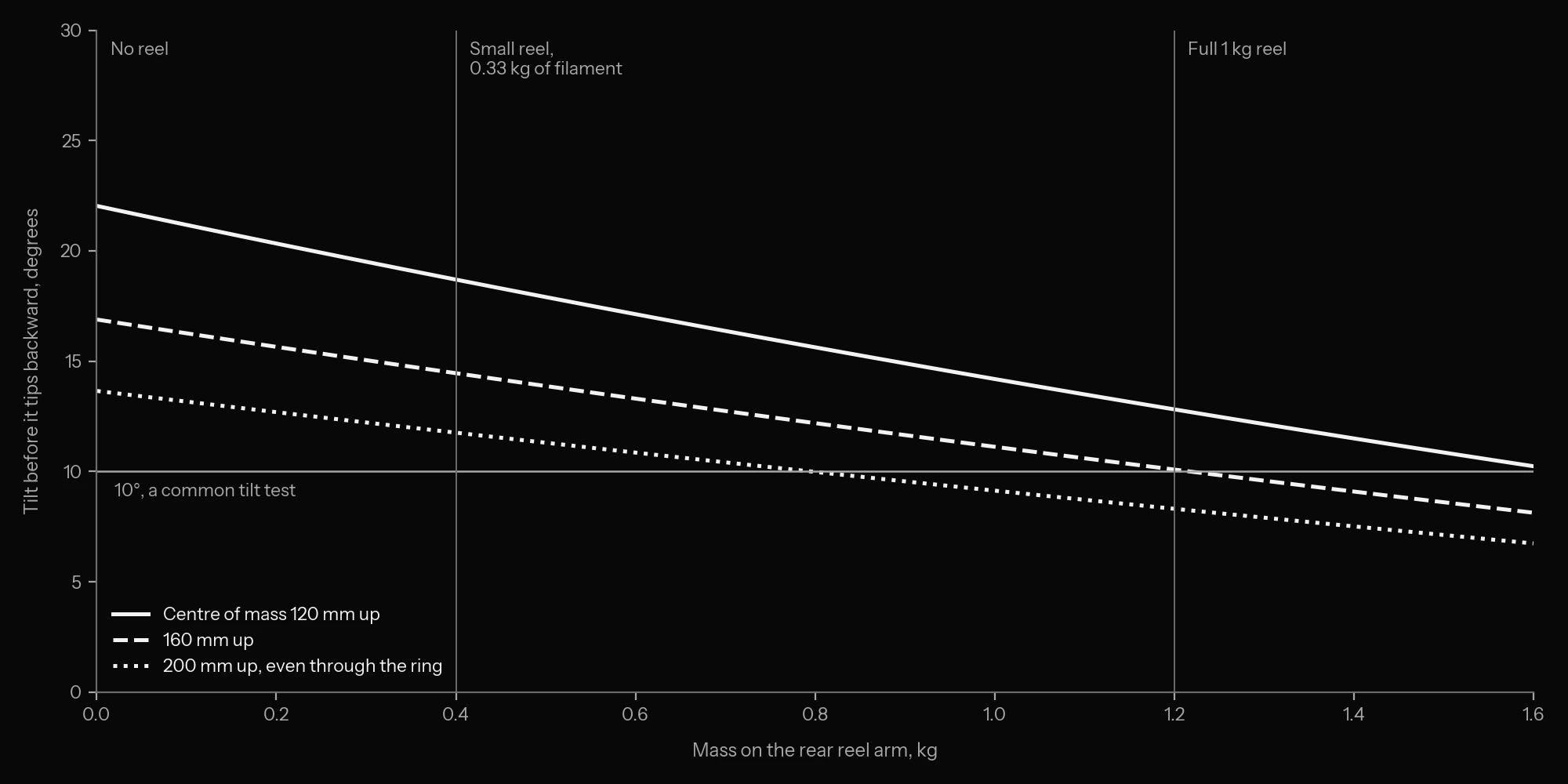
The printer stands on a base plate 243 mm wide and 97 mm deep, under a housing 117 mm deep. In the model a full-size reel hangs on an arm at the back, its centre 233 mm behind the front face. With the manual's 9.5 kg at mid-depth, the printer alone tips backward at 14° if its mass is spread evenly through the ring and at 22° if it is bottom-heavy. A full 1 kg reel, taken as 1.2 kg with its flanges, brings that to between 8° and 13°.
IEC 62368-1 and IEC 60335-1 both use a 10° tilt test, as test-equipment suppliers summarise them, and 60335-1 raises it to 15° for appliances with heating elements. Whether either applies to a 3D printer is not settled here. These are the numbers for the model. The reviews describe a small reel inside the frame, which would not move the centre of mass this way.
Housing walls
The four shells are solid. Their walls run 15 mm at the median and 7 mm at the thinnest 5 percent. Protolabs recommends 1.1 to 3.6 mm for moulded ABS, so the shells are four to thirteen times thicker than a moulder would draw them. Between 41 and 88 percent of their surface has less than 1° of draft, depending on the direction they are pulled from the mould, where Protolabs advises 0.5° on vertical faces and 1 to 2° in most cases. The 2019 model does not say how the shells are made.
Method and sources
Every figure in the studies comes from the 2019 KeyShot export of the model, an OBJ file with 57 named objects and 1.6 million vertices. One file unit is 100 mm: the housing then measures 398 × 400 mm against the manual's 40 × 40 cm, and the rods 6 mm. The measurements were made in 2026 in Blender by casting rays against the mesh. The casing band, the print system and the travel position were also modelled in Blender in 2026. None of them enters the measurements, which use the housing of the 2019 model and, for the plate and the nozzle, its positions. The loads, the current, the heat and the airflow are hand calculations and one OpenFOAM case on the model, with their inputs named in their own section. The 2026 parts, cables included, were checked for intersections with the housing and with each other, and each axis was swept through its travel in Blender, with the pinion turned against the rack at 47 positions of the bed. The cables were checked in place and not swept. The head has 192 mm of travel along the beam, the beam and head have 126 mm of height, and the bed slides 140 mm between its stops, which covers the manual's 190 × 135 × 125 mm build volume. The cables and the filament are fixed props and do not flex.
The studies look back at the model, not at the printer as it shipped. The 2019 model has no mass, physical material data, wiring, power supply or boards, so the tilt study takes its mass from the manual and varies the height of the centre of mass. The population data are US and Dutch and the furniture heights come from supplier summaries of EN 527-1 and EN 1729-1. The sources checked give no Portuguese eye-height or hand data and no measured noise figure for the printer.
- The BEETHEFIRST quick start guide, 2014, for the size, the mass, the nozzle and the safety notes.
- The Make review and the PCMag review, both 2014, for the nozzle temperature and the reel.
- The HIWIN MG series catalogue, pages 82 and 86, for the ratings and stiffness of the 9 mm rail blocks.
- Catalogue pages for the reference motors, a NEMA 8, a NEMA 14 and a NEMA 17 pancake; for the 6 mm GT2 belt, Phidgets and On-Drives; and for 25 mm fans, Coolerguys, RA-DC2510H and Delta.
- PLA, ABS and PTFE on Wikipedia, for glass transitions, conductivity and the PTFE limit, and OpenFOAM v2512 for the airflow case.
- ANSUR II for adult seated eye height and hand size, and NHANES 2015 to 2018 for stature and body weight.
- Snyder et al. 1977, through the NIST AnthroKids files, for children's eye height and hands, and DINED for adult standing eye height.
- NIOSH Applications Manual 94-110 and the NIOSH Easy Ergonomics booklet for handle sizes.
- CENELEC Guide 29 for burn thresholds, and a CEN HEARD summary of ISO 13857 for safety distances.
- The ISO 9241-5 preview for line of sight, and the Protolabs moulding guidelines for wall thickness and draft.
Impact of the design on the 3D printing industry
In 2011, 3D printers were mostly seen as DIY, plywood constructions, with a focus on functionality rather than aesthetics. As the designer of BEETHEFIRST, I believed that 3D printers could be more than just functional tools, but could also be consumer electronic products with a more appealing design. My bet paid off, as the BEETHEFIRST's visually appealing design was widely embraced in the industry and helped shift the perception of 3D printers from just functional tools to consumer electronics.
Many 3D printer companies have followed in the footsteps of BEETHEFIRST and have designed their products with a more consumer-friendly look.
- Year
- 2011
- Field
- Product
- Role
- Sole designer, master’s thesis
- With
- Beeverycreative