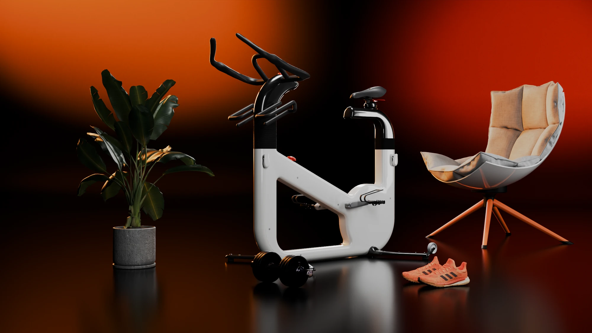
uBike
Smart home fitness bike
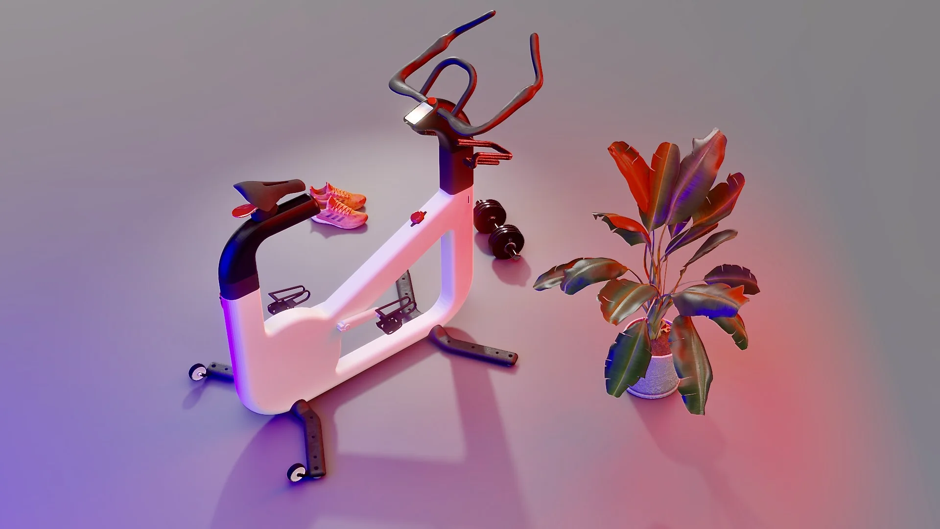
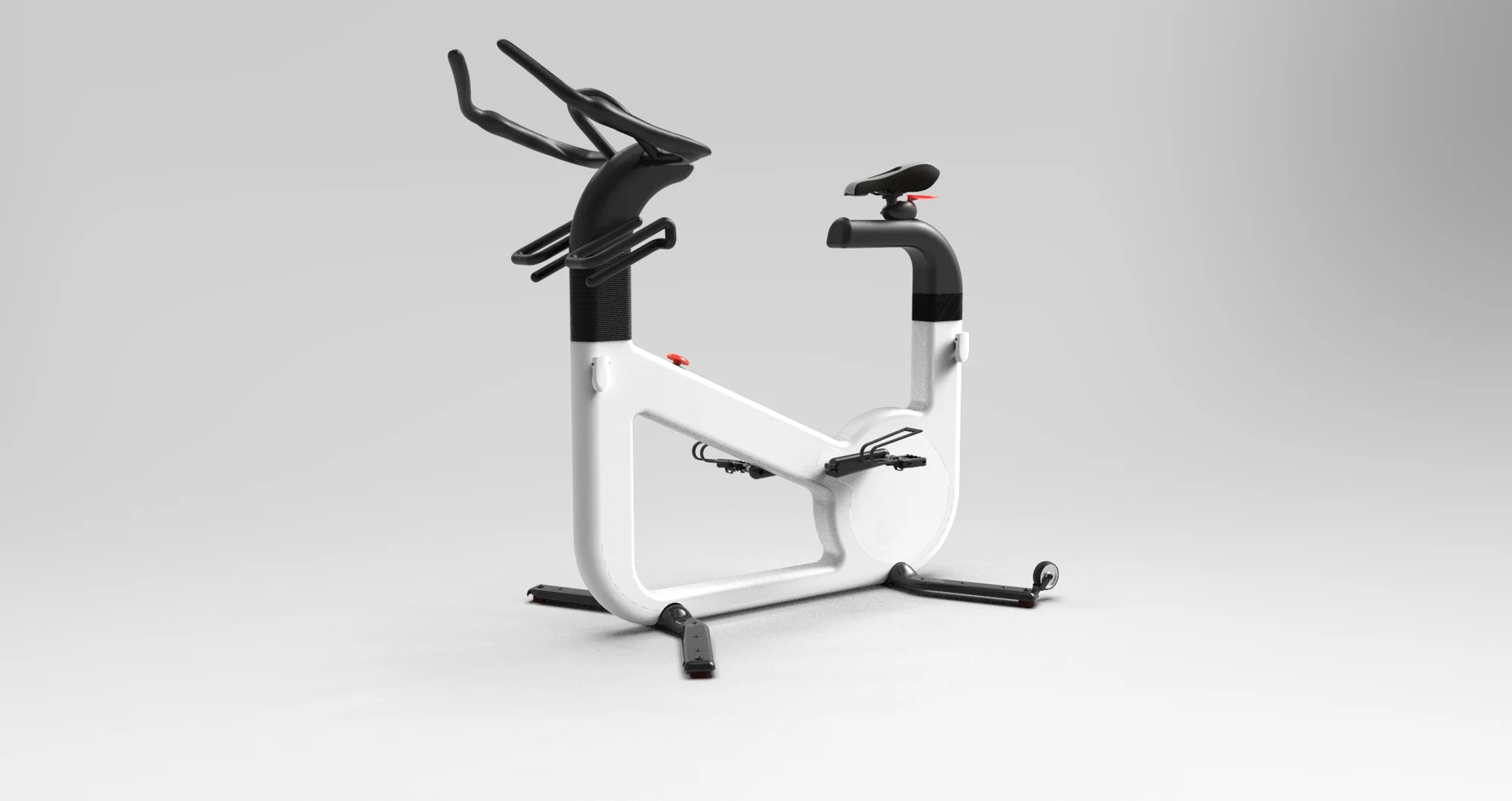
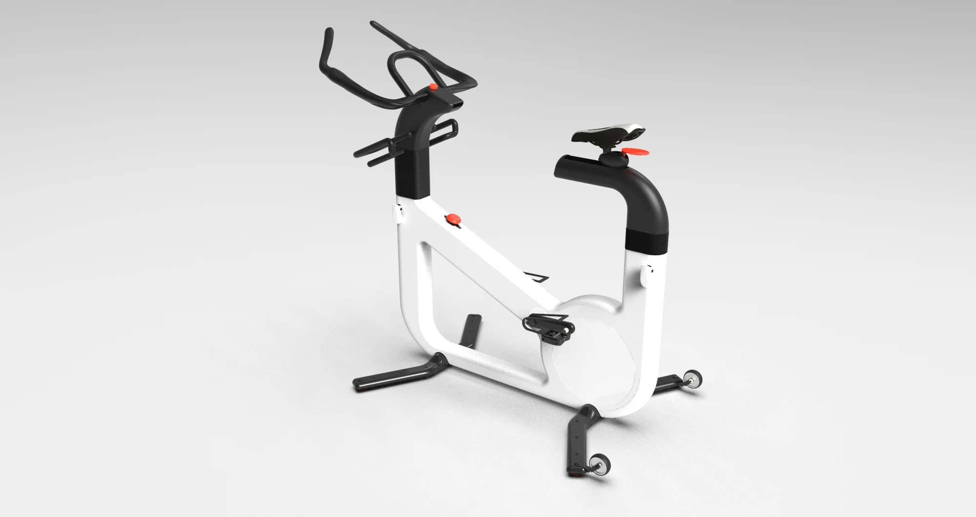
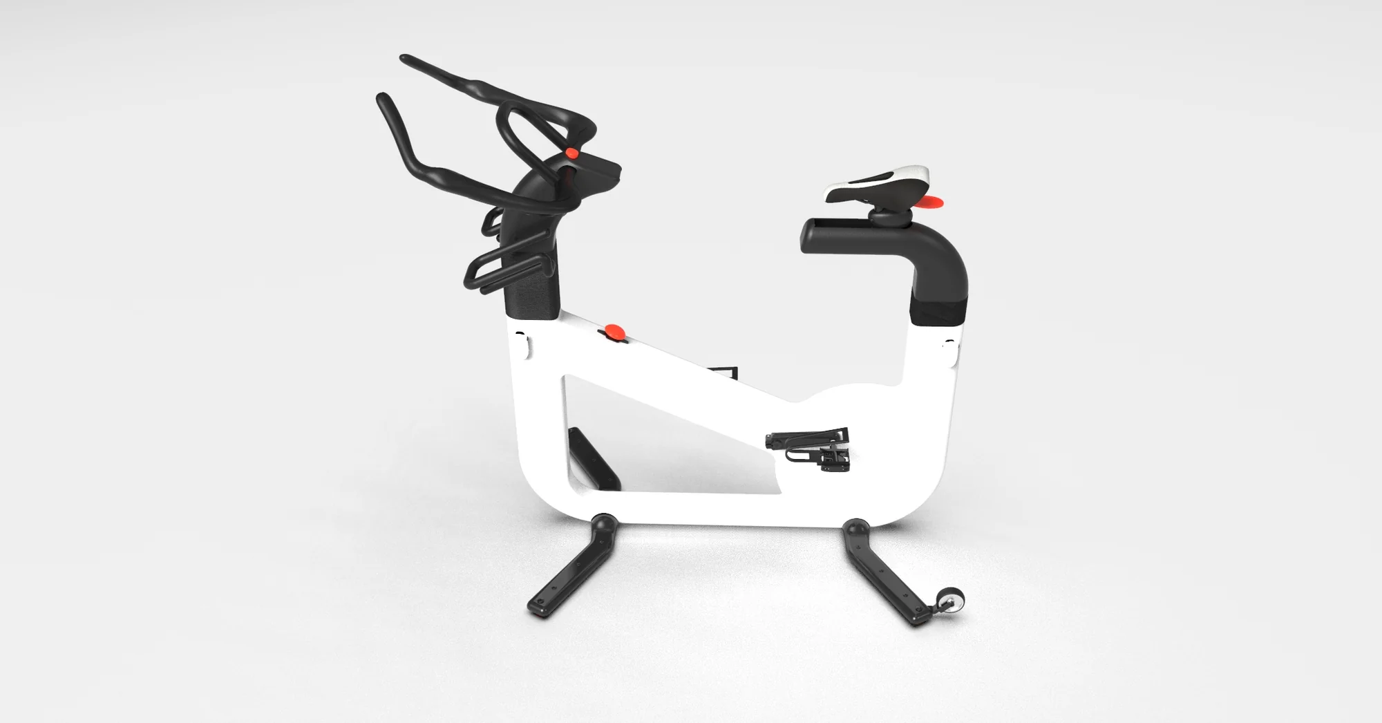
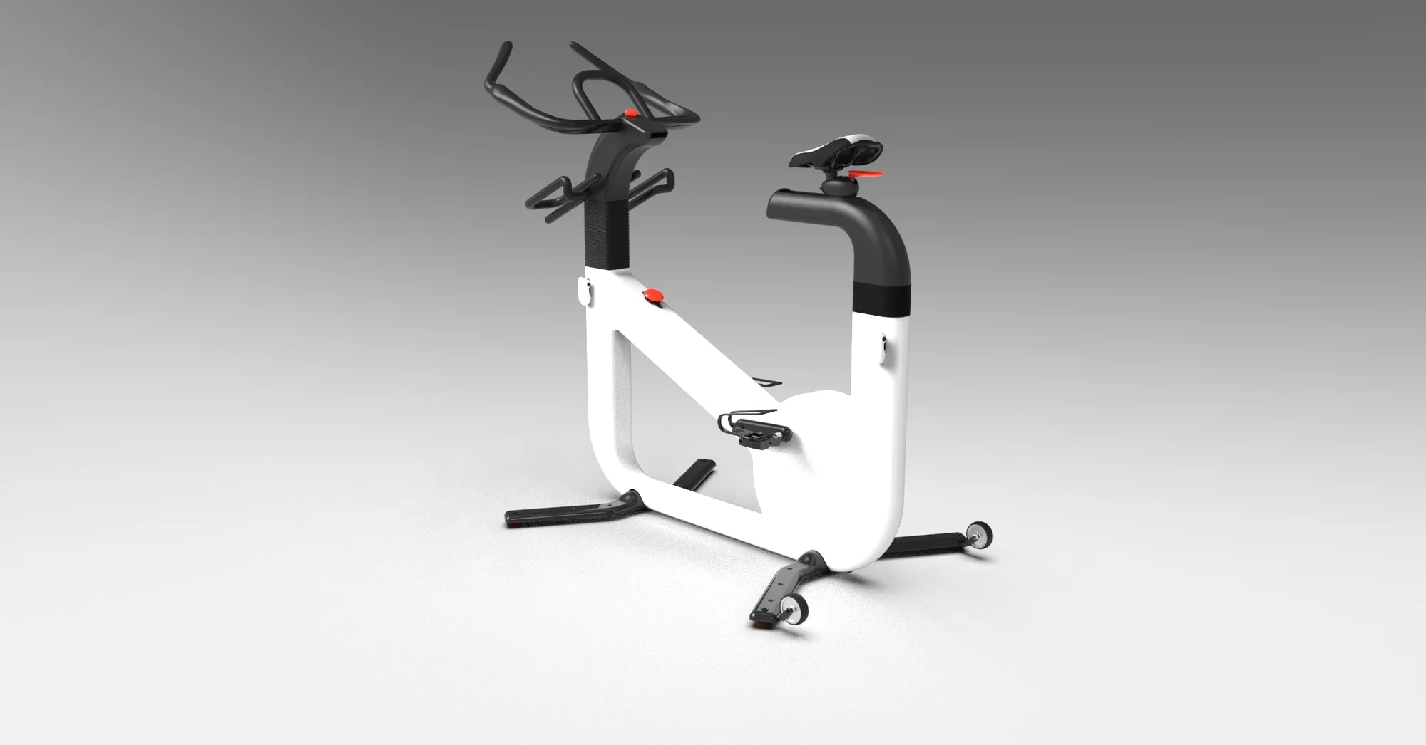
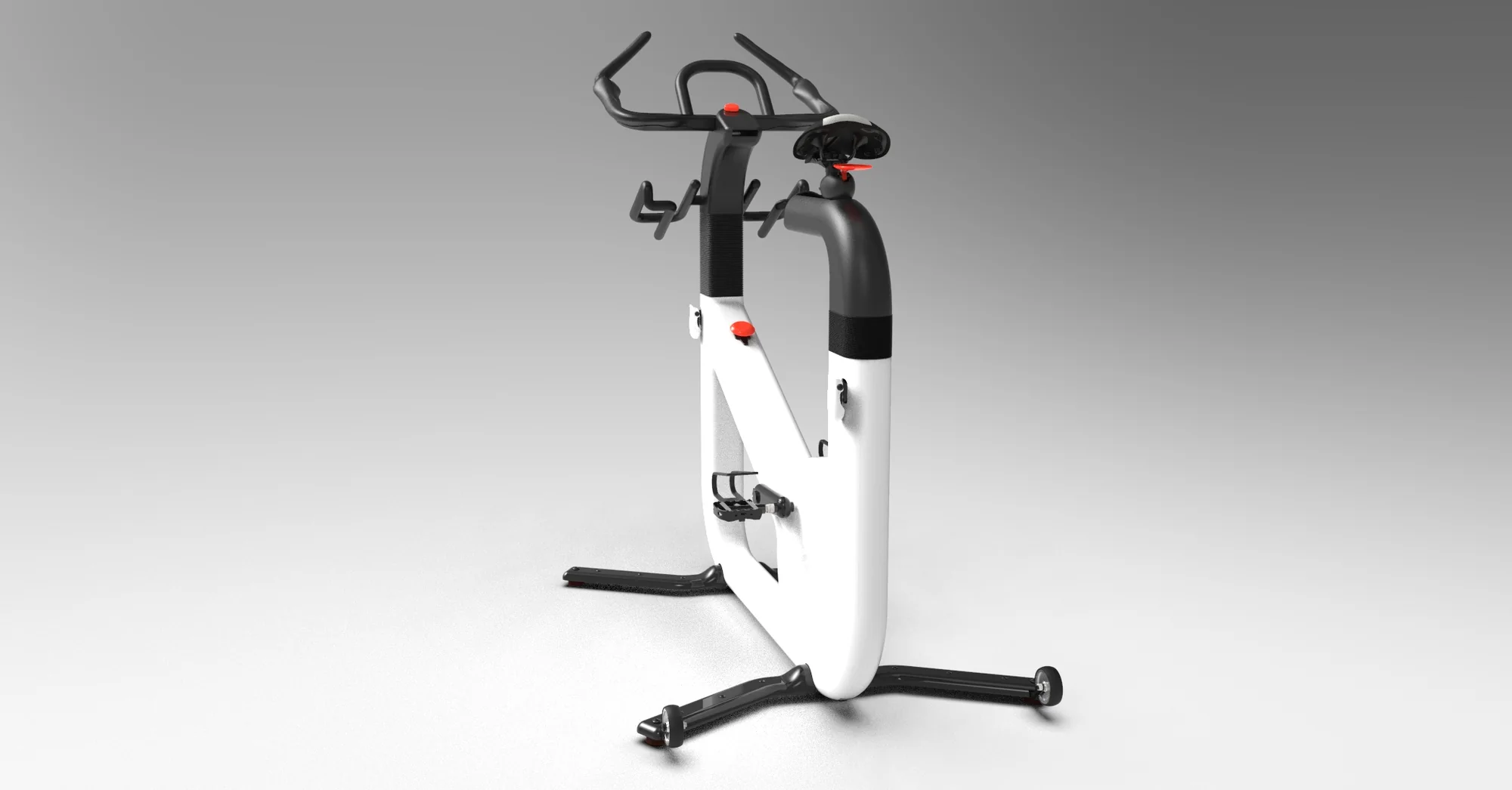
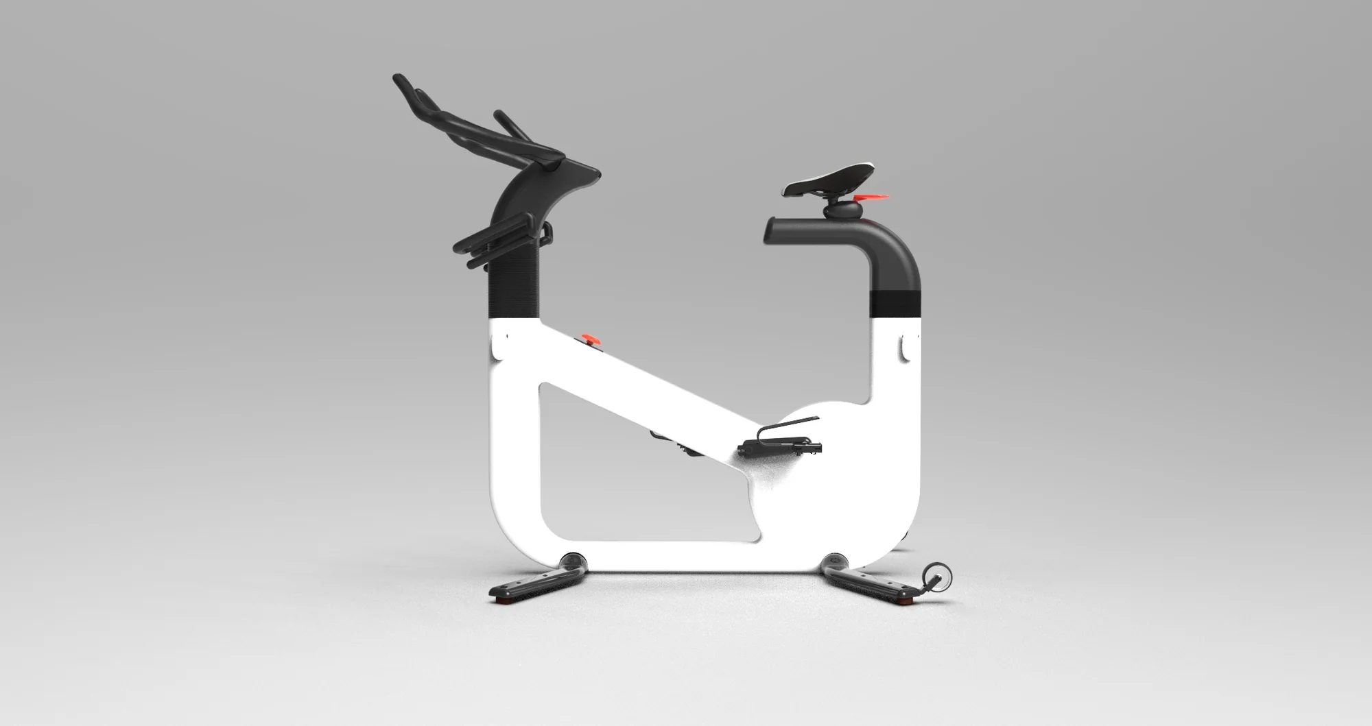
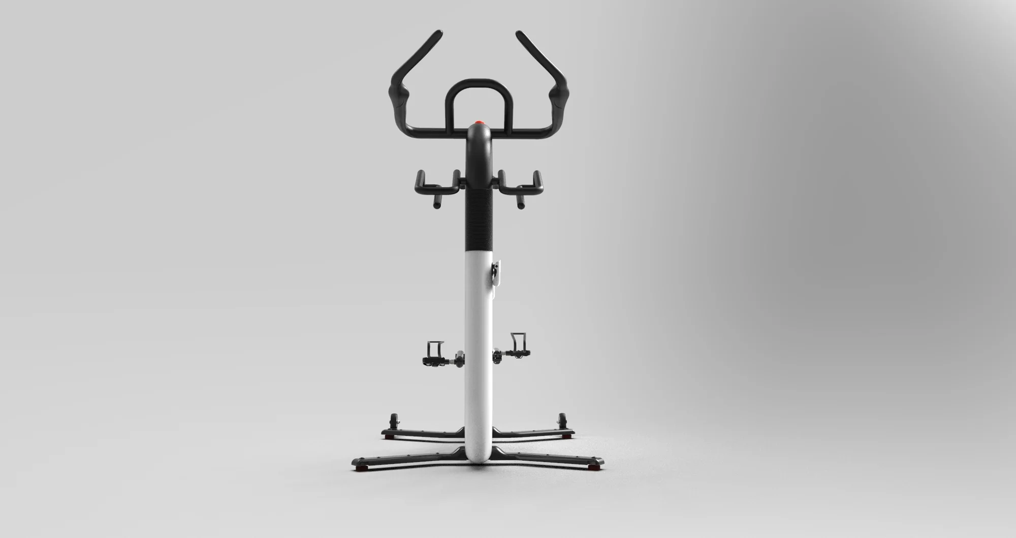
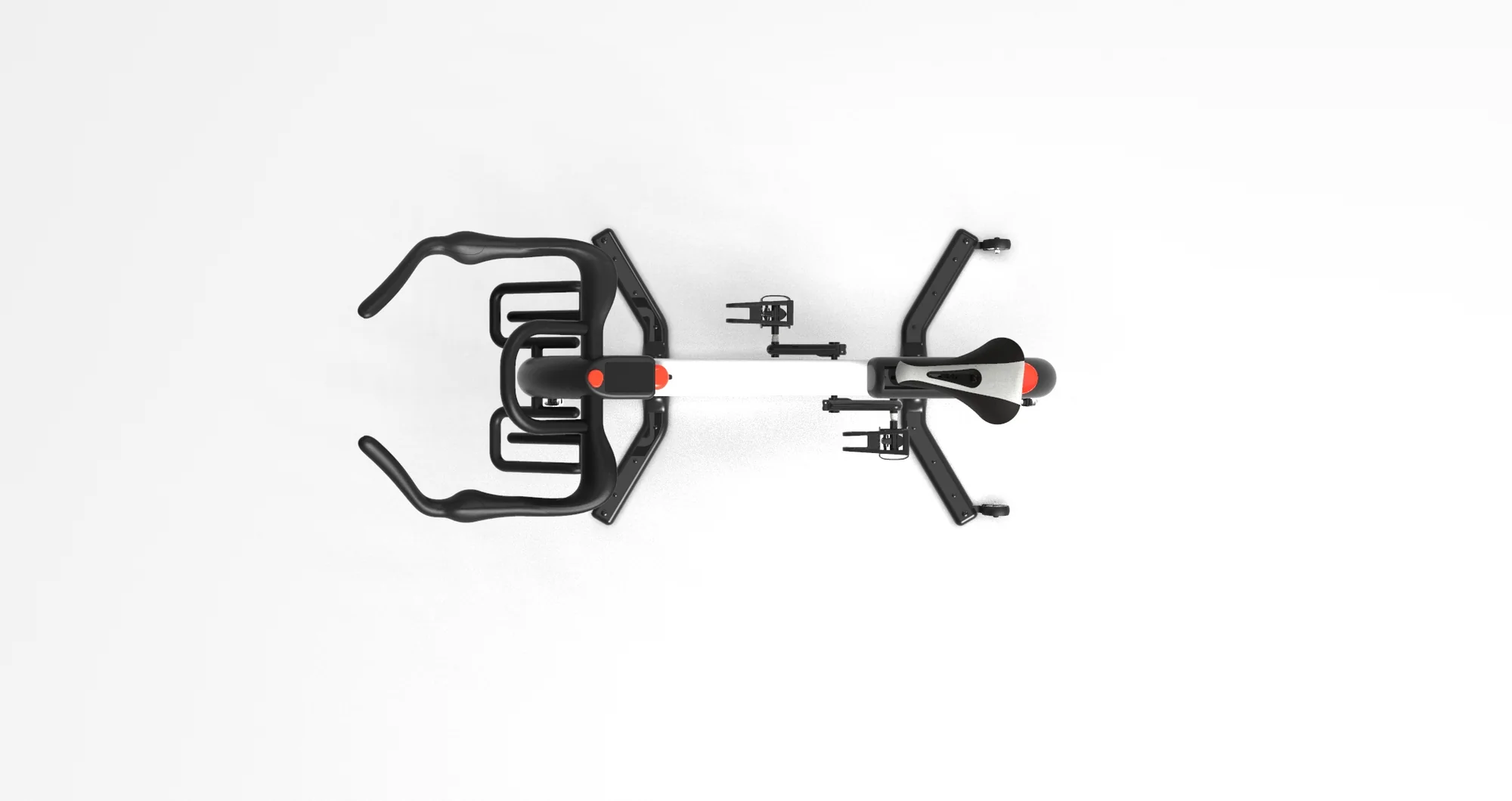
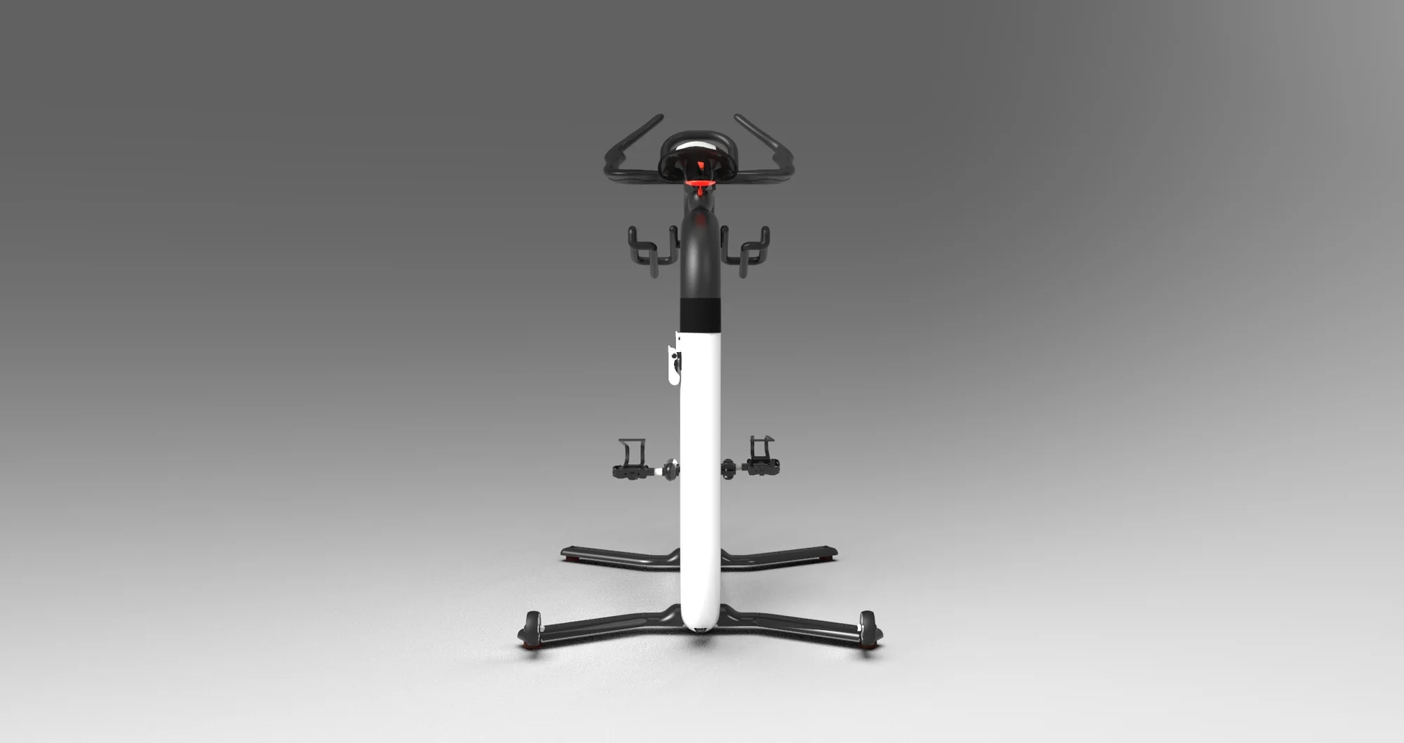
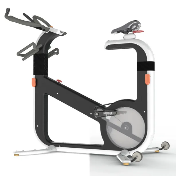
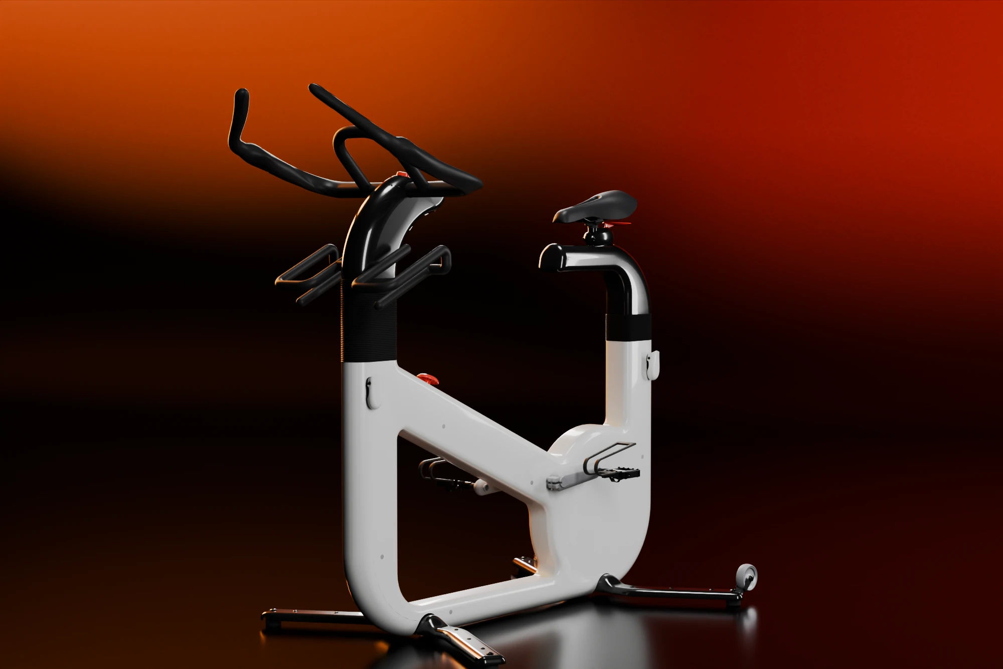
uBike is an indoor bike I designed with Gregorio Rodrigues, for the gym and for the home. The idea was one machine that makes its own electricity from the pedals and shows the ride on a screen connected to the internet.
We began with the mechanical concept, then the functional one: how the bike would be used and what features it needed. The form followed. The press covered it in 2011 and 2012 as a bike with a panel display and software that tracks the workout.
In 2026 I went back to the 3D model and tested it the way an engineer would test a product: does it fit people, does it stand up, does the energy claim hold, what would break first. A v2 answers what the tests found. The original model was never changed; the v2 is edits to its mesh, and its mechanisms are sketches.
The 2026 tests were done with two AI agents, Claude and Codex, which wrote the analysis scripts. I set the questions and checked every result.
The model at true scale
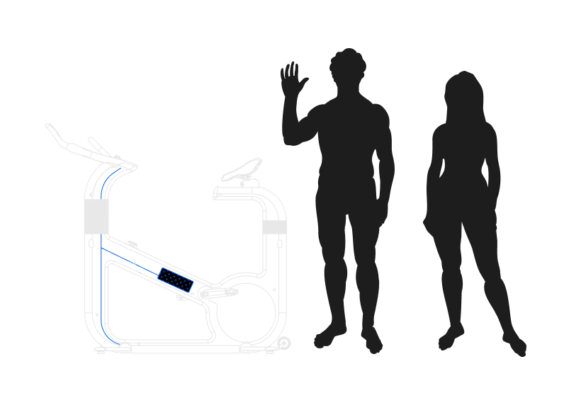
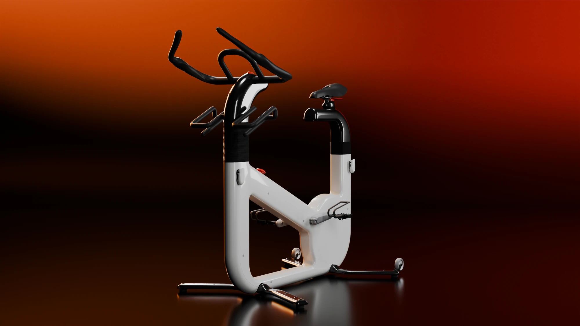
The model has no units. Its nuts, screws, washers and bearings are standard parts, so their proportions fix the scale: one unit is 0.3411 m, to within a quarter of a percent across nine parts. The mesh also had flipped faces on 146 of its 346 parts and 83 exact duplicates, so I rebuilt every volume part by part. The mirrored shell halves I checked now agree to within a percent.
From the model, at true scale
- Size, width × height × length
- 829 × 1,364 × 1,452 mm
- Saddle top above the floor
- 1,136 mm
- Crank length
- 152 mm
- Frame
- Two moulded shells, 2.9 mm walls
- Flywheel
- Solid disc, Ø339 × 26 mm
- Footprint, outer edges of the pads
- 1,043 × 797 mm
- Mass, estimated
- 26 to 70 kg
The mass is a range because the model carries no materials. The low end is an aluminium flywheel and plastic shells, the high end a steel flywheel and a die-cast frame, and both include an allowance for the display, wiring and covers that are not modelled.
Does it fit people
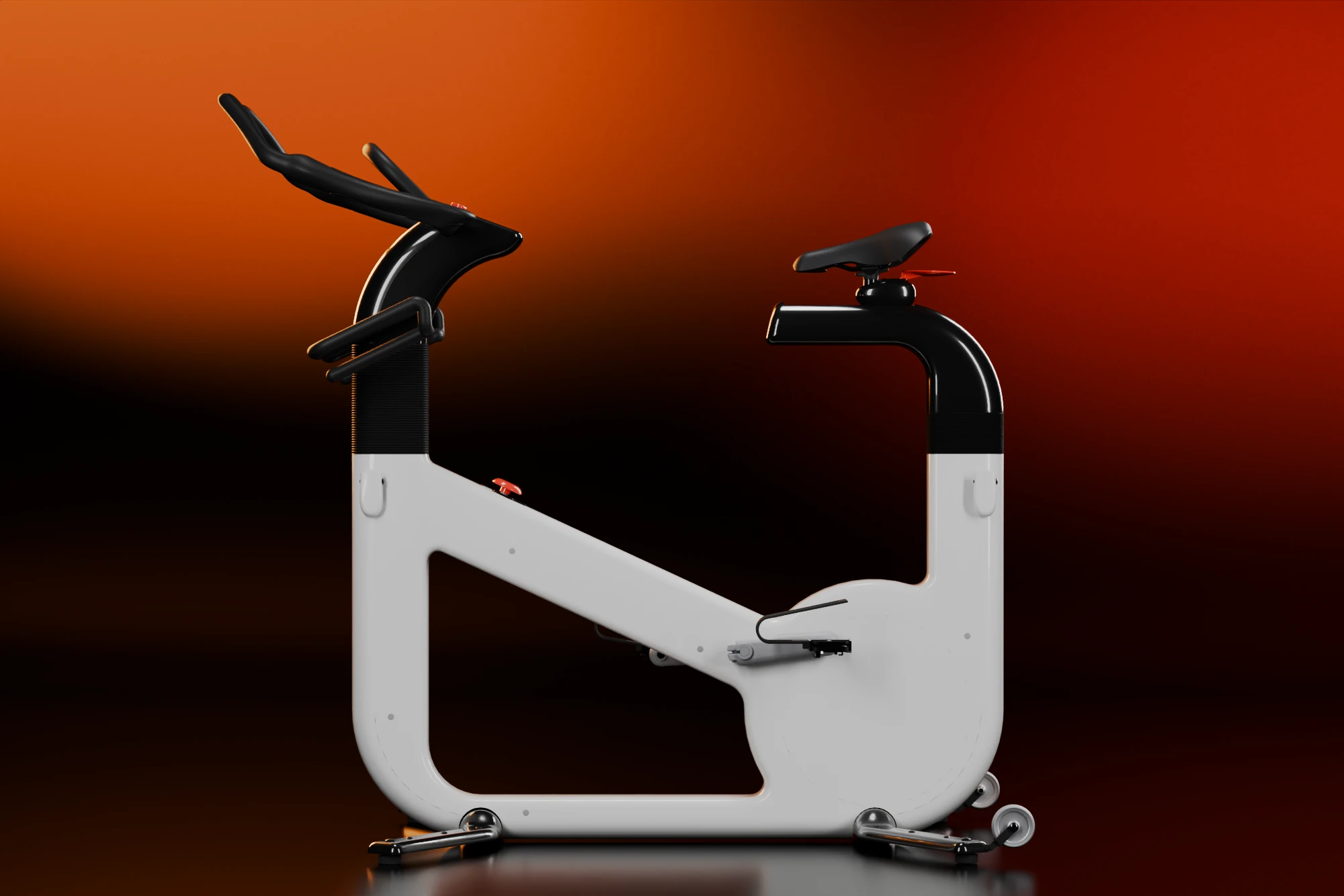
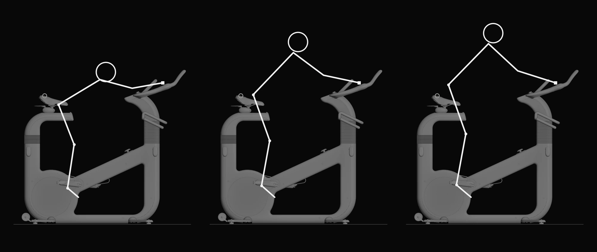
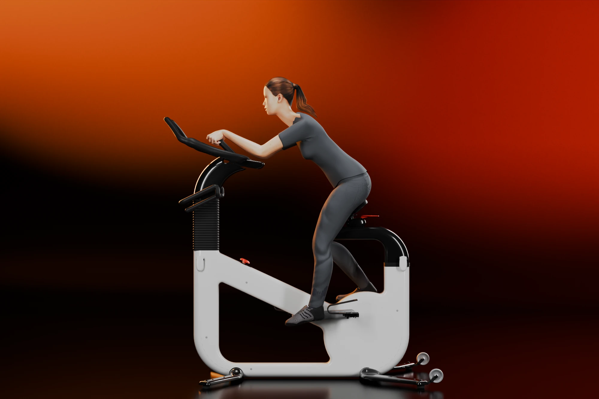
I fitted the bike to 6,068 measured adults from the ANSUR II survey, 4,082 men and 1,986 women, using each person's own leg, trunk and arm lengths. A rider is a side view: the knee bent 25 to 35 degrees at the bottom of the stroke, the elbows 10 to 45 degrees bent at the grips. ANSUR II is a US Army sample, so the percentages are indicative.
The original saddle is 783 mm above the bottom bracket, the pedal axle, which suits a rider about 1.82 m tall. Seventy per cent of adults need it lower, and a woman shorter than 95 per cent of women needs it 149 mm lower. It is also too far back, and the median rider needs it 79 mm further forward. On the handlebar, nine riders in ten can use only the first 180 mm of the 476 mm sloped arm. On the original, the smallest rider has to lean 59 degrees to reach the middle of the bar.
A v2 with adjusters
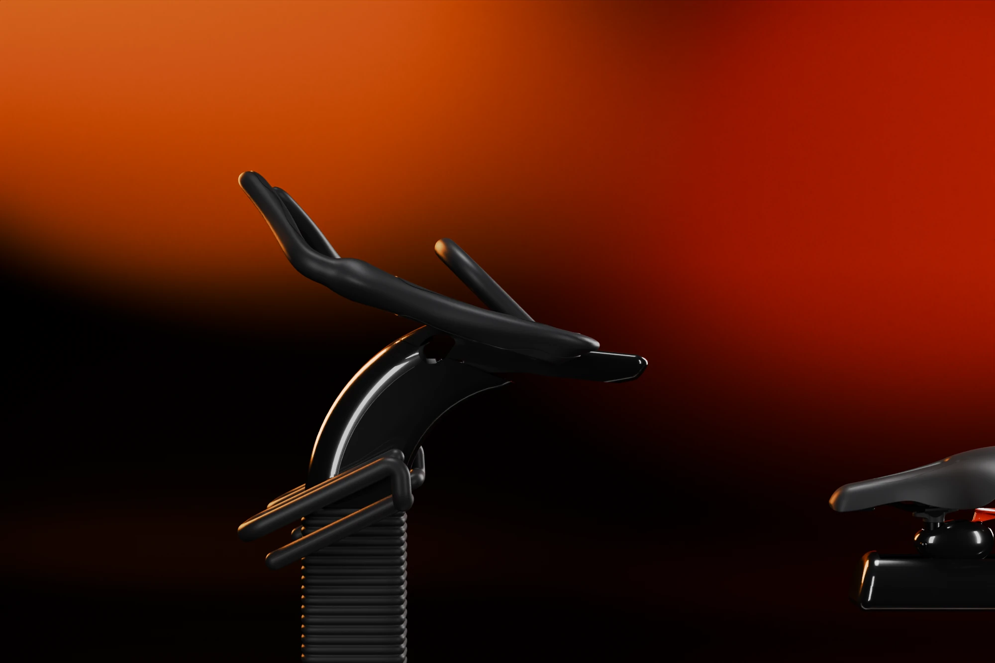
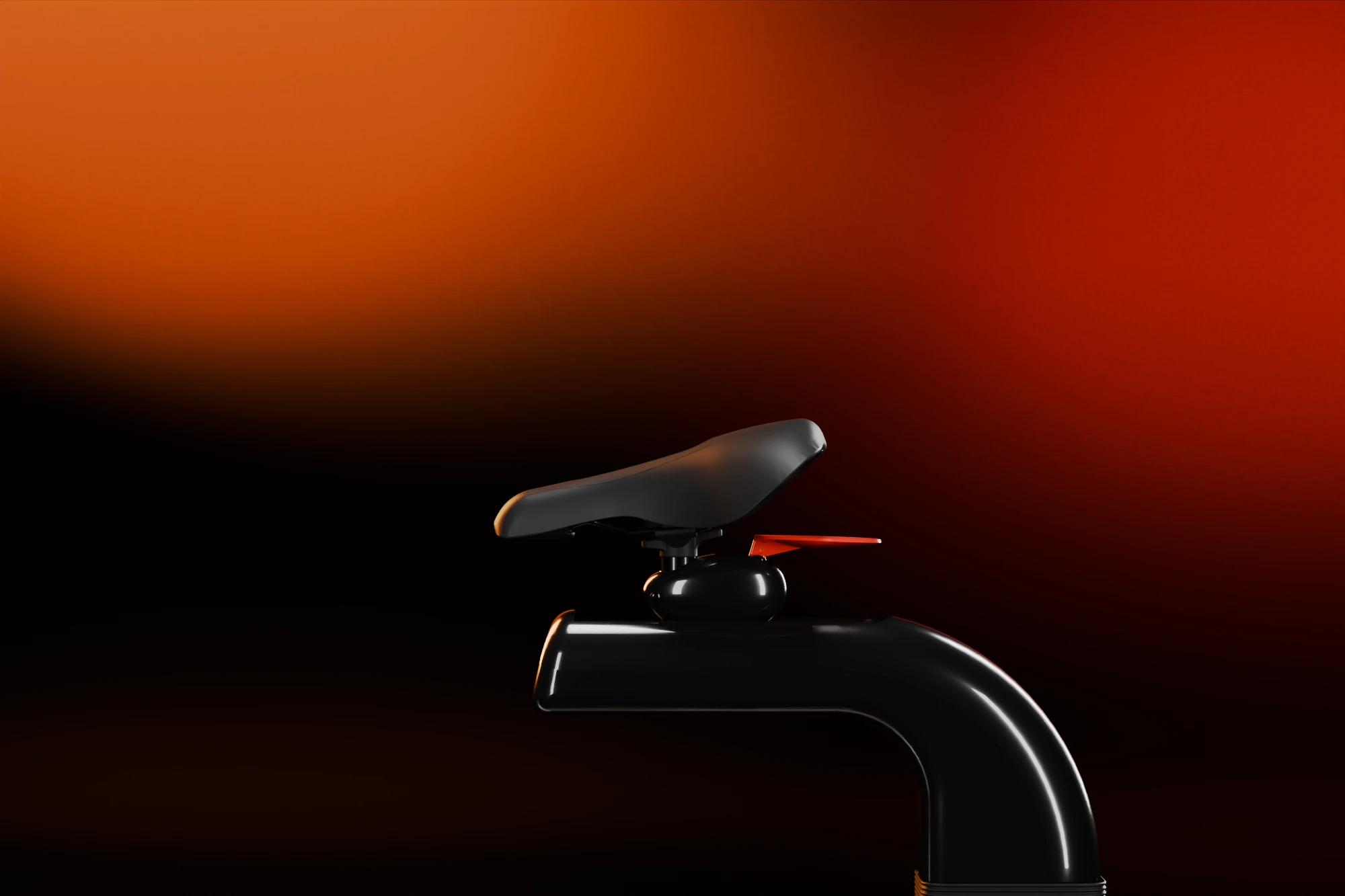
The model carries adjuster hardware: ribbed boots where the black arms leave the columns, a clamp lever on each column just below the boot, and a clamp under the saddle. It carries no travel for any of them, and nothing that moves the bar towards the rider. So I tested what the hardware could do if its travel were generous. With 240 mm of saddle height, 40 mm of saddle fore-aft and 200 mm of bar height, at most about 32 per cent of riders get a good saddle and all three grip postures. The bar is the limit, because it can only go up and down.
The v2 keeps the columns and the two trays and adds three controls.
- The saddle height runs over 240 mm, and the black arm telescopes further into its column behind a longer boot.
- The saddle sits 80 mm further forward than on the original and slides 40 mm either way on its tray.
- The handlebar is 80 mm higher and slides on the front tray, from 20 mm forward of the original reach to 160 mm back. The tray telescopes with it, so nothing sticks out behind the clamp at the original reach.
With the same fit model, 96.9 per cent of the 6,068 adults get a good saddle position and all three postures, upright, neutral and sport. The shortfall is at the extremes: a variant with 280 mm of saddle height and 50 mm of forward and back travel would reach 98.9 per cent, at the cost of a longer telescoping sleeve. As modelled, the original fits none of them. The fit model gives each rider's saddle height, how far forward or back the saddle sits, and how far the handlebar slides.
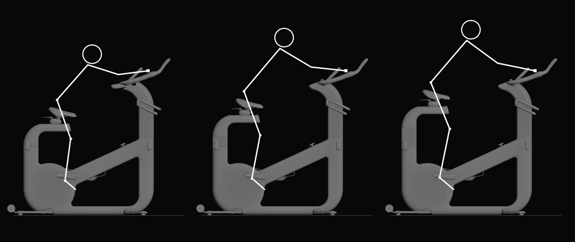
per cent of adults with a good saddle and all three grip postures
Does it stand up
I treated the machine as a rigid body on its four rubber pads and put a rider on it, seated or standing, 100 kg or 150 kg, in the light, central and heavy builds that the mass range allows. None of them tips on a 10 degree incline, in any direction. The weak direction is backwards: the saddle is only 102 mm ahead of the rear pads. In the lightest build with a 150 kg rider the margin is 11.5 degrees. The 10 degree incline is how I read the stability requirement of ISO 20957-1 from excerpts; the standard's own procedure has not been checked.
The v2 adds to the margin in two ways. Moving the saddle forward for fit adds about two degrees. Lengthening the rear feet by 125 mm adds five more, so the same worst case becomes 18.9 degrees.
The two transport wheels sit behind the rear pads with their bottoms 26 mm off the floor, so the machine has to be tipped back 17.5 degrees before they touch, and then needs 10 to 33 kgf at the grips depending on the build. Wheels near the centre of gravity would cut that by more than half, but fixed wheels there would never reach the floor. They would have to be lowered with a foot lever. The v2 leaves the wheels where they are; they ride out with the longer feet.
What the generator can do
In the model the pedals drive a flywheel by chain, and a belt then drives a small gearbox and a motor that I read as the generator. I assumed a converter after it. With the losses I assumed, about 69 per cent of the rider's power comes out as electricity between 100 and 300 W, and only 43 per cent at 30 W, where the generator's fixed loss dominates. An 18 W display and radio, which is my assumption, runs from 36 W of pedalling.
watt-hours
- An 18 W display and radio
- Left over
So the claim holds. The bike powers its own screen with something to spare: at a steady 165 W it makes about 114 Wh in an hour, 96 Wh more than the display and radio use.
What would break first
The drivetrain is a 45-tooth chainring on a 9-tooth sprocket, which turns the flywheel five times for each pedal turn. A belt then drives a gearbox and the generator. The model has no chain or belt, so I took their size from the sprockets and pulleys.
Loads in the original
- Pedal shaft Ø17 mm, bending, 400 and 1,000 N
- 119 and 296 MPa
- Fatigue limit I allow for steel
- about 150 MPa
- Chain tension at 150, 300 and 1,000 W
- 0.28, 0.83 and 1.39 kN
- Chain breaking strength, 8 mm pitch
- about 4.4 kN
- Bearing seat load at 2 kN on a pedal
- 10.4 kN
- Flywheel at the crank, aluminium and steel
- 2.3 and 6.6 kg m²
- Needed for a smooth stroke at 150 W
- 3.6 kg m²
The pedal shaft is the problem. It is a solid Ø17 mm bar with the pedal 143 mm outboard of the bearing, and a rider standing on one pedal puts about twice the allowable stress into it. It needs to be 24 mm or more, or the lever has to be shorter. The chain is fine for an ordinary ride and at its limit in a 1,000 W sprint, with a 4 kN peak against about 4.4 kN, and the 9-tooth sprocket gives the chain a 6 per cent speed variation at every tooth. The flywheel is a solid disc. In steel it passes the smooth-stroke test on its own, and in aluminium it does not unless the generator's rotor adds inertia behind the belt.
The moulded shells are 2.9 mm thick, and the front column, taken as a beam, carries 11 MPa at its root for each kN at the grips. That suits glass-filled nylon or die-cast aluminium better than ABS. The bearing seat takes 20 MPa at a 2 kN pedal force and has to be metal.
Proposed changes
- A pedal shaft of at least 24 mm, with a metal housing for the bearings.
- A 3/8 inch chain, or a toothed belt, and no 9-tooth sprocket.
- An inertia of at least 3.6 kg m² at the crank, from a steel flywheel, a defined rotor and gearbox, or electronic inertia that the generator can supply.
- The v2 adjusters, with their travel and loads checked against ISO 20957.
- Wheels that lower near the centre of gravity, and rear feet that slide out for riding and in for storing instead of a fixed longer foot.
- Arms in glass-filled nylon or die-cast aluminium.
The model does not give the materials, the motor, the gearbox ratio or the real adjuster travel; those are in the SolidWorks assembly. The fit is a model of a side view, not a test with riders, and the strength figures are first-order beam theory, not finite elements. All of it was computed from the geometry with Python, and the renders on this page were made in Blender.
The 2011 renders